Waste collection device

A waste collection and collection box technology, which is applied to metal processing machinery parts, maintenance and safety accessories, metal processing equipment, etc., can solve the problems of low lathe combination, inconvenient height lifting, complex structure, etc., to achieve safe and stable movement, dumping The process saves labor and facilitates the effect of height adjustment

Inactive Publication Date: 2018-05-15
ANHUI RUIZHIXIN INFORMATION TECH CO LTD
View PDF10 Cites 2 Cited by
  • Summary
  • Abstract
  • Description
  • Claims
  • Application Information

AI Technical Summary

Problems solved by technology

[0005] In order to overcome the disadvantages of complex structure, low integration with lathes, and inconvenient height lifting in the existing background technology, the present invention provides the following technical solutions:

Method used


Image

  • Waste collection device
  • Waste collection device
  • Waste collection device

Examples


Embodiment Construction

[0021] The following will clearly and completely describe the technical solutions in the embodiments of the present invention with reference to the accompanying drawings in the embodiments of the present invention. Obviously, the described embodiments are only some of the embodiments of the present invention, not all of them. Based on the embodiments of the present invention, all other embodiments obtained by persons of ordinary skill in the art without making creative efforts belong to the protection scope of the present invention.

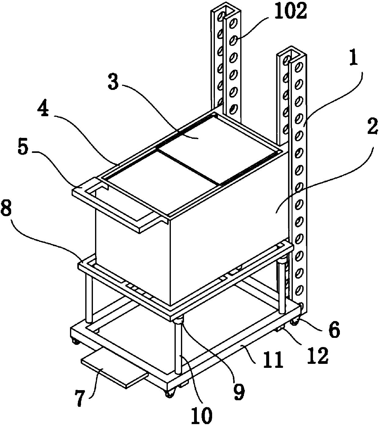
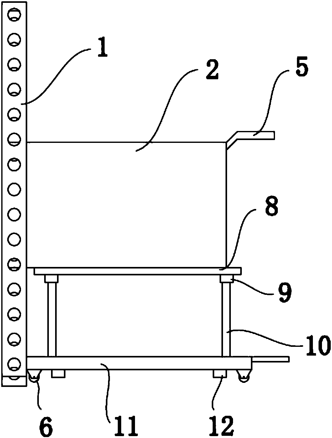
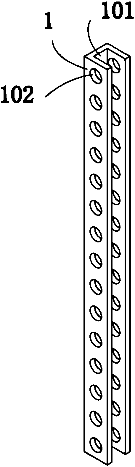
[0022] see Figure 1-8

[0023] Such as Figure 1-5 A waste collection device shown includes a guide rail 1, a collection box 2, and a sliding door 3. The guide rail 1 is fixed on the lathe discharge port, the guide rail 1 is vertically fixed on the ground, and the surface of the collection box 2 is provided with a protrusion 201 to collect The box 2 is fixed on the guide rail 1 through the sliding fit of the protrusion 201 and the groove 101, ...


PUM


Abstract

The invention discloses a waste collection device. The waste collection device comprises guide rails, a collection box and pull doors. The guide rails are fixed to a discharging opening of a lathe. The guide rails are vertically fixed to the ground. The collection box is fixed to the guide rails in a sliding fit manner. A double-layer sliding rail is arranged on the top of the collection box. Thepull doors are slidably arranged on the double-layer sliding rail. A handle is arranged on the surface of the collection box. A lifting device is fixedly arranged at the bottom of the collection box.Rolling wheels are arranged at the bottom of the lifting device. A pedal is fixedly arranged on one side of the lifting device. According to the waste collection device, by arranging the lifting device, height adjustment of the collection box is facilitated so as to make the collection box better combined with the discharging opening of the lathe, and the lifting height of hydraulic rods can be changed by adjusting hydraulic control valves, so that the dumping angle of the collection box is changed, the time and labor are saved, the situations that the workshop environment is contaminated andsafety accidents are caused due to waste chipping splashing are avoided by arranging the pull doors, and the structure is simple.

Description

technical field [0001] The invention relates to the technical field of mechanical processing equipment, in particular to a waste material collection device. Background technique [0002] At present, in the field of machinery manufacturing and processing, the processing of parts is generally completed through processes such as turning, milling, planing, and grinding. Therefore, when processing parts, a large amount of chips, especially iron filings, etc. will be generated. Collected, it can be recycled, avoiding the waste of raw materials and reducing production costs, but if good iron filings collection measures cannot be taken, it will cause iron filings to splash, which may pollute the environment of the production workshop and lead to failure of mechanical equipment. Even cause safety accidents. [0003] The existing patent CN107285068A provides a cutting iron chip collection device, which adopts electric drive and has the characteristics of cleanness, environmental prot...

Claims


Application Information

Patent Timeline
Patent Type & Authority Applications(China)
IPC IPC(8): B23Q11/00B23Q11/08
CPCB23Q11/0067B23Q11/08
Inventor 李夫马敏
Owner ANHUI RUIZHIXIN INFORMATION TECH CO LTD
Why Eureka
Try Eureka