
Vehicle supporting bridge pipe and end face flange welding machine and welding method thereof

A flange and bridge tube technology, which is applied in the field of welding equipment for supporting bridge tubes and flanges and their welding, can solve the problems of large welding workload, heavy tasks, and difficult to guarantee welding quality, so as to reduce welding deformation and improve coaxiality. The effect of improving the welding quality

Active Publication Date: 2018-05-15
ANYANG INST OF TECH
View PDF8 Cites 58 Cited by
  • Summary
  • Abstract
  • Description
  • Claims
  • Application Information

AI Technical Summary

Problems solved by technology

[0002] One end of the vehicle support bridge tube is fixedly connected to the rear axle housing, and the other end is welded with a flange. The flange is used to install the brake drum. The inner hole of the support tube supports the wheel shaft to ensure the coaxiality of the flange and the vehicle support tube, which can extend the life of the brake drum. service life, improve the braking effect when braking, because the welding workload between the support bridge tube and the flange is heavy, the task is heavy, and the economic efficiency is low, many enterprises adopt welding automation level is not high, and the welding quality is difficult to guarantee

Method used


Image

  • Vehicle supporting bridge pipe and end face flange welding machine and welding method thereof
  • Vehicle supporting bridge pipe and end face flange welding machine and welding method thereof
  • Vehicle supporting bridge pipe and end face flange welding machine and welding method thereof

Examples


Embodiment Construction

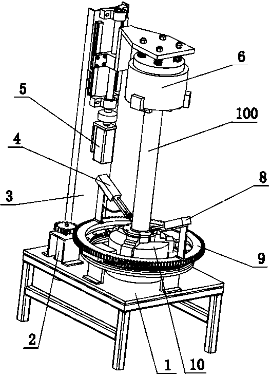
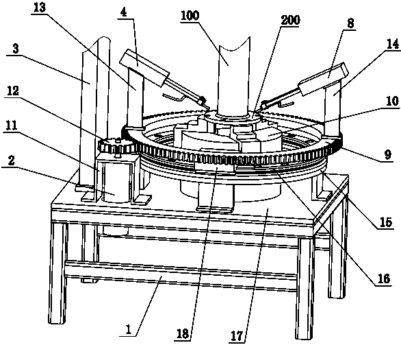
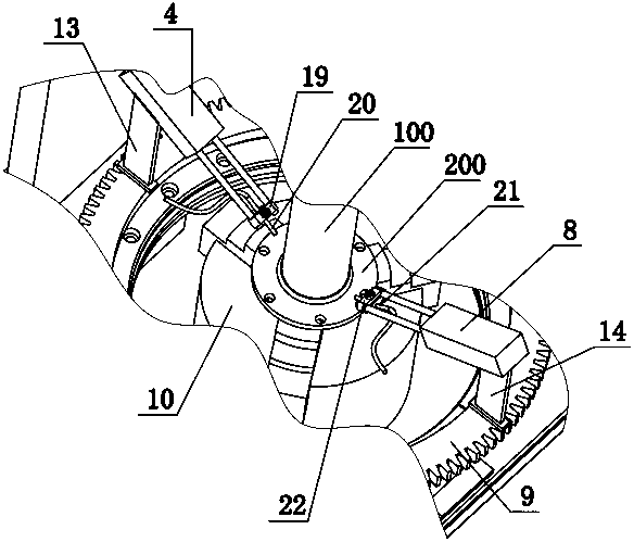
[0031] combine Figure 1~6 , a vehicle support bridge tube and end face flange welding machine of the present invention includes a welding seat 1, a servo motor 2, a vertical beam 3, a double-rod cylinder 4, a servo motor 2 5, a three-jaw chuck 6, a double rod Cylinder two 8, ring gear 9, three-jaw chuck two 10, motor frame one 11, gear 12, cylinder frame one 13, cylinder frame two 14, guide rail frame 15, ring guide rail 16, support plate 17, slider one 18, Welding torch fixing block one 19, welding torch one 20, welding torch two 21, welding torch fixing block two 22, motor frame two 23, shaft coupling 24, bearing housing one 25, lead screw 26, slide block two 27, lead screw nut 28, Linear guide rail one 29, bearing housing two 30, lower pressure plate 31, stud 32, lock nut 33, spring 34, connecting plate 35, linear guide rail two 36, slider two 37, the upper end of the welding seat 1 is fixedly supported Flat plate 17, support flat plate 17 is arranged along horizontal dir...


PUM


Abstract

The invention provides a vehicle supporting bridge pipe and end face flange welding machine and a welding method thereof. The welding machine comprises a welding seat, a supporting flange plate is fixed at the upper end of the welding seat, a second three-claw chuck is fixed on the supporting flat plate, a circumferential rotating device coaxial with the second three-claw chuck is arranged on thesupporting flat plate, two welding guns are fixed on two sides of the center of the circumferential rotating device, a vertical beam is fixed on the supporting flat plate, a lifting mechanism is fixedon the vertical beam and fixed to a first three-claw chuck through elastic connection, a second three-claw chuck and the first three-claw chuck are fixed to a flange and a supporting bridge pipe respectively, and the welding guns weld the flange and the bridge pipe when rotating. The welding guns with two circumferential sides in symmetry are adopted to weld a welding position at the same time, welding deformation of the supporting pipe and the flange caused by welding stress is reduced, and coaxiality between the supporting pipe and the flange is improved.

Description

technical field [0001] The invention relates to a support bridge tube and flange welding equipment and a welding method thereof, in particular to a vehicle support bridge tube and end face flange welding machine and a welding method thereof. Background technique [0002] One end of the vehicle support bridge tube is fixedly connected to the rear axle housing, and the other end is welded with a flange. The flange is used to install the brake drum. The inner hole of the support tube supports the wheel shaft to ensure the coaxiality of the flange and the vehicle support tube, which can extend the life of the brake drum. service life and improve the braking effect when braking. Due to the heavy workload, heavy tasks and low economic efficiency of the welding between the supporting bridge tube and the flange, many enterprises use welding with a low level of automation, and the welding quality is difficult to guarantee. [0003] In this application, the lower side three-jaw chuck ...

Claims


Application Information

Patent Timeline
IPC IPC(8): B23K37/04B23K37/053B23K37/02
CPCB23K37/02B23K37/0211B23K37/04B23K37/0443B23K37/053B23K37/0533
Inventor 马洪儒王丙军吴贵军国秀丽吕掌权
Owner ANYANG INST OF TECH
Learn More