Electrostatic chuck device
An electrostatic chuck and electrostatic adsorption technology, applied in the direction of holding devices, positioning devices, circuits, etc., which apply electrostatic attraction, can solve the problems of product life reduction, wafer temperature unevenness, component warping, etc., and achieve uniform heat Sexuality improvement, the effect of inhibiting free radical erosion
- Summary
- Abstract
- Description
- Claims
- Application Information
AI Technical Summary
Problems solved by technology
Method used
Image
Examples
no. 1 Embodiment approach
[0047] (Electrostatic Chuck Device)
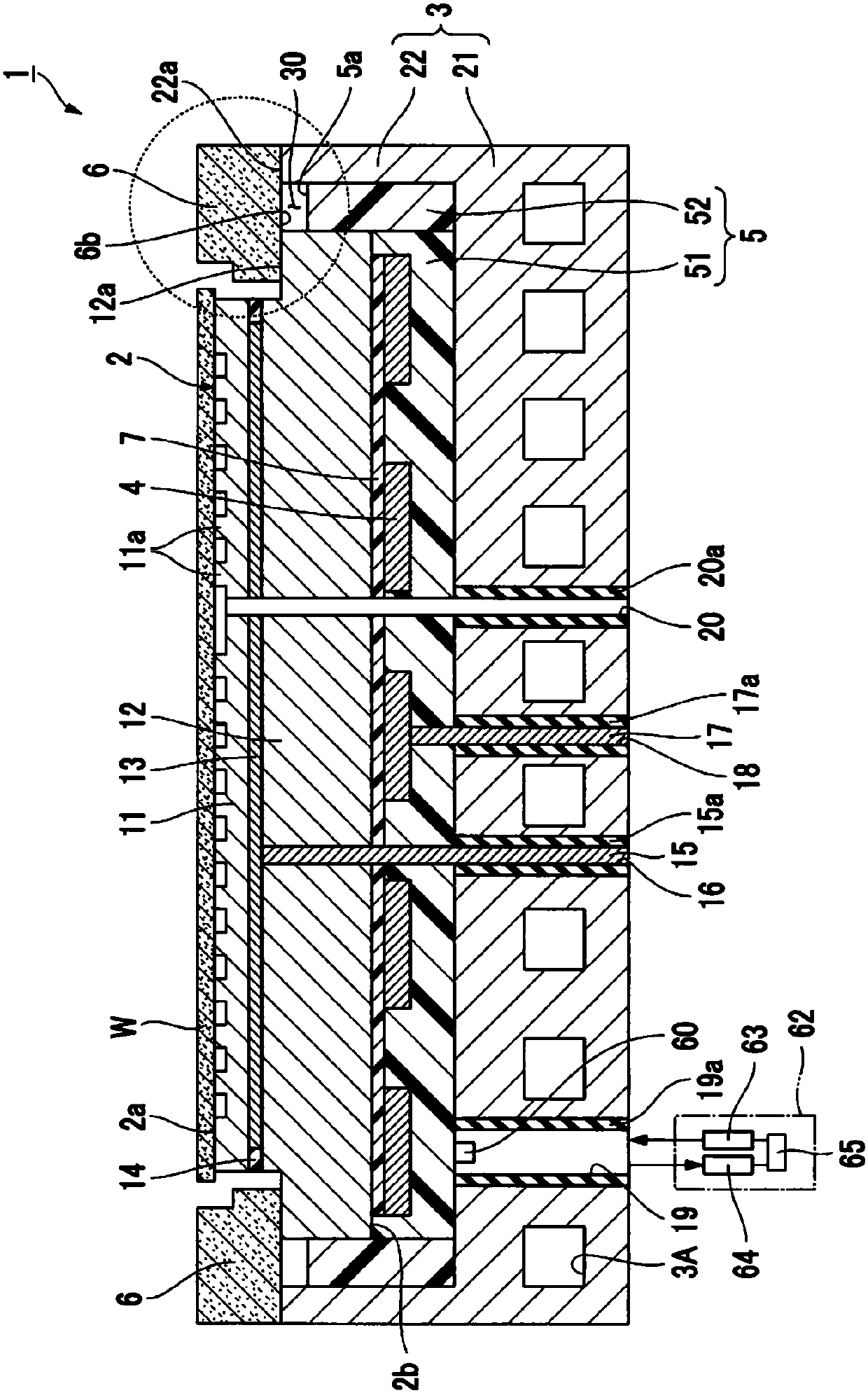
[0048] figure 1 It is a sectional view showing the electrostatic chuck device according to the first embodiment which is a preferable example of the present invention. The electrostatic chuck device 1 of this form includes an electrostatic chuck unit 2 , a base unit 3 for temperature adjustment, a heater element 4 , an adhesive unit 5 , and a focus ring 6 .
[0049] The electrostatic chuck unit 2 has a mounting plate 11 , a support plate 12 , an electrode for electrostatic adsorption (internal electrode for electrostatic adsorption) 13 , and an insulating material layer 14 . The mounting plate 11 has a mounting surface on which a plate-shaped sample W such as a semiconductor wafer is mounted on its upper surface. The supporting plate 12 is integral with the placing plate 11 and supports the bottom side of the placing plate 11 . Electrodes for electrostatic adsorption (internal electrodes for electrostatic adsorption) 13 are provided bet...
no. 2 Embodiment approach
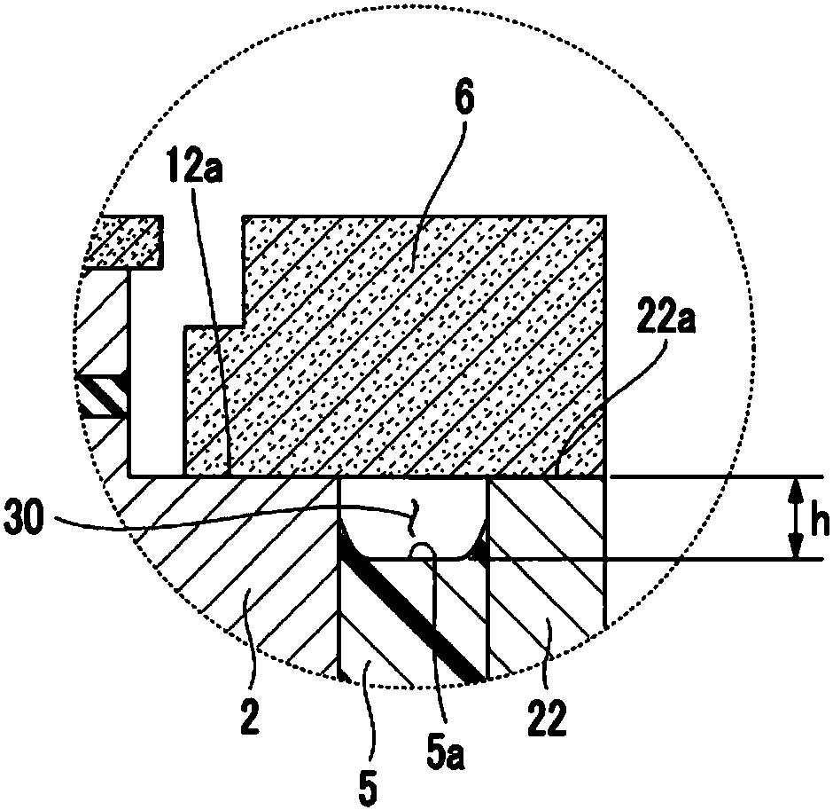
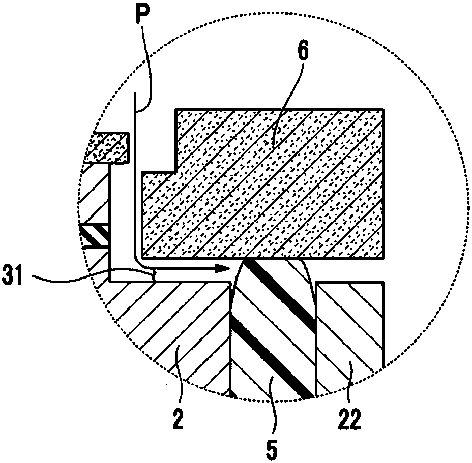
[0117] Figure 4 It is an enlarged schematic cross-sectional view of the vicinity of the focus ring in the electrostatic chuck device according to the second embodiment of the present invention. The electrostatic chuck device 101 according to the second embodiment differs from the electrostatic chuck device 1 according to the first embodiment only in that the electrostatic chuck part 2, the focus ring 6, the bonding part 5 and the bank part The space 32 surrounded by 22 is not a closed space, but a partly opened space. Therefore, in the following description, the configuration of the space will be described in detail, and the description of common parts will be omitted. And, in each drawing for explanation, for the Figure 1 ~ Figure 3 The same symbols are attached to the common constituent elements.
[0118] In the electrostatic chuck device 101 , the focus ring 6 is supported by the upper surface of the periphery of the electrostatic chuck unit 2 . Therefore, a gap is form...
no. 3 Embodiment approach
[0125] Next, the third embodiment of the present invention will be described, but the description will focus on the differences from the first embodiment and the second embodiment, and the description of the same matters will be omitted.
[0126] (Electrostatic Chuck Device)
[0127] Preferably, the coefficient of thermal expansion of the first region 51 is smaller than the coefficient of thermal expansion of the second region 52 .
[0128] This is because the second region 51 is likely to affect the in-plane heat uniformity of the plate-shaped sample W placed on the electrostatic chuck unit 2 . For example, when the first region 51 is made of a silicone resin with a filler, and the second region 52 is made of a silicone resin without a filler, since the first region 51 has a filler with a small coefficient of thermal expansion, the first region 51 The coefficient of thermal expansion is smaller than that of the second region 52 .
[0129] Furthermore, the first region 51 pr...
PUM
 Abstract
Description
Claims
Application Information
 - R&D Engineer
- R&D Manager
- IP Professional
- Industry Leading Data Capabilities
- Powerful AI technology
- Patent DNA Extraction
Browse by: Latest US Patents, China's latest patents, Technical Efficacy Thesaurus, Application Domain, Technology Topic, Popular Technical Reports.
© 2024 PatSnap. All rights reserved.Legal|Privacy policy|Modern Slavery Act Transparency Statement|Sitemap|About US| Contact US: help@patsnap.com


