
Accurate and efficient clamping fixture applied to low-speed wire cutting machining and clamping splicing table

A slow wire-moving and precise technology, applied in the field of tooling and fixtures, can solve the problems that fixtures and fixtures cannot be assembled to form a workbench, cannot guarantee machining accuracy and quality, and cannot achieve long-term remote operation, so as to ensure machining accuracy. And processing quality, small space occupation, small error effect

Pending Publication Date: 2018-05-11
中山市凯鸿精密模具有限公司
View PDF0 Cites 2 Cited by
  • Summary
  • Abstract
  • Description
  • Claims
  • Application Information

AI Technical Summary

Problems solved by technology

[0004] The purpose of the present invention is to overcome the problems that the existing fixtures are very prone to when fixing the workpiece, such as the parts are not fixed stably, cannot be clamped accurately and efficiently, the error of repeated clamping is large, and displacement occurs during the processing, and the processing accuracy and quality cannot be guaranteed. Processing quality, there is also the possibility of parts flying out of the equipment, which poses a great safety hazard. At the same time, fixtures and fixtures cannot be assembled to form a workbench, and slow wire processing equipment cannot automatically process multiple parts. Next to the equipment, the parts are frequently clamped, the efficiency is low, and the technical problems of long-term remote operation cannot be realized. It provides accurate and efficient clamping fixtures and clamping and assembling tables for slow-moving wire processing.

Method used


Image

  • Accurate and efficient clamping fixture applied to low-speed wire cutting machining and clamping splicing table
  • Accurate and efficient clamping fixture applied to low-speed wire cutting machining and clamping splicing table
  • Accurate and efficient clamping fixture applied to low-speed wire cutting machining and clamping splicing table

Examples


Embodiment Construction

[0030] The composition, technical problems and beneficial effects of the present invention will be further described in detail below in conjunction with the accompanying drawings. It should be understood that the specific embodiments described here are only used to explain the present invention, and are not intended to limit the scope of the present invention.

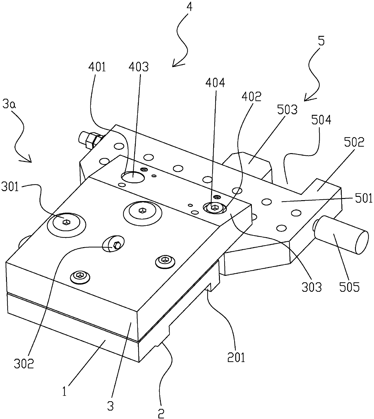
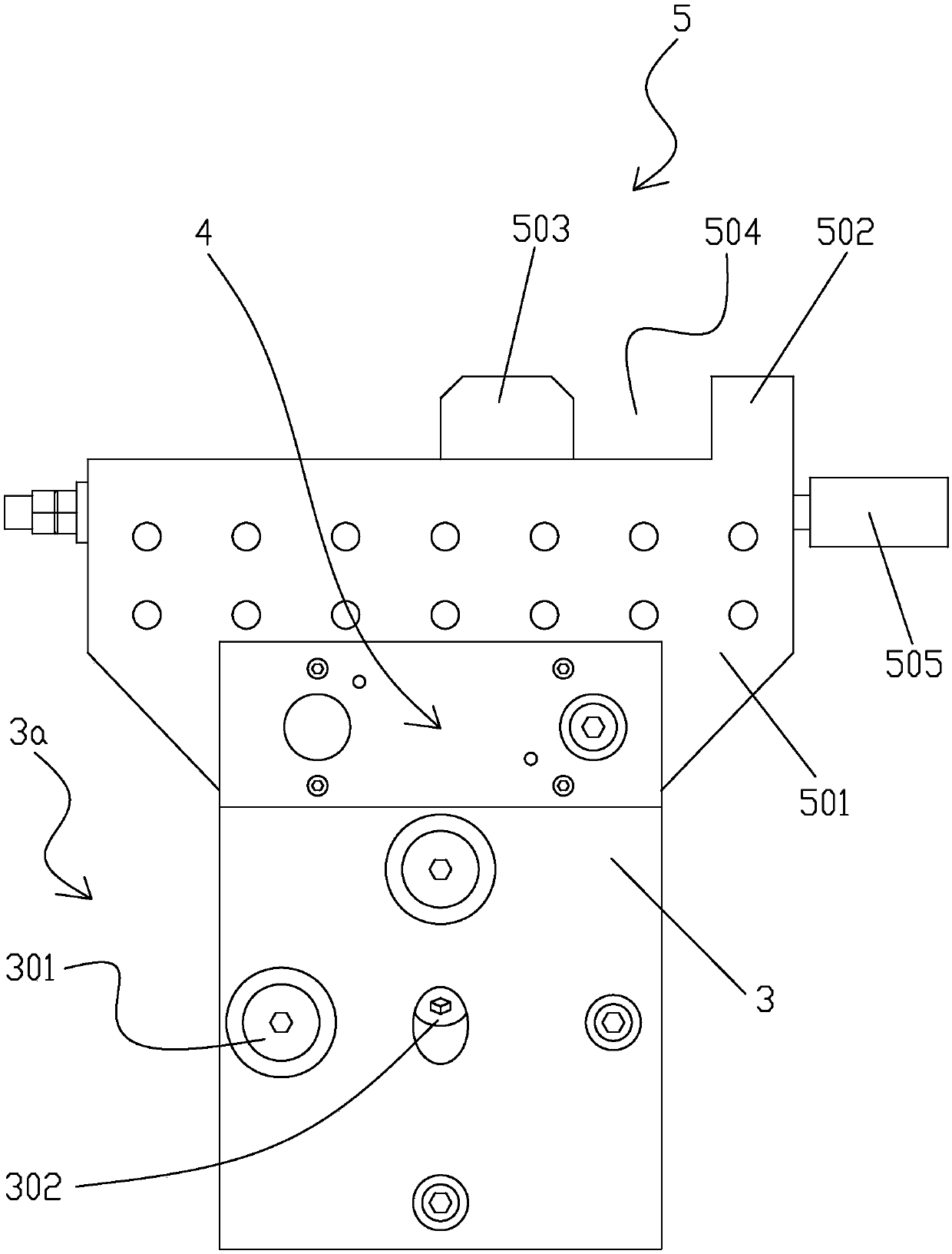
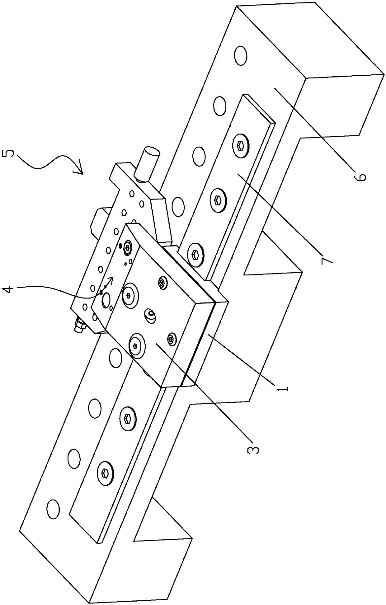
[0031] Such as figure 1 , figure 2 As shown, the present invention discloses a precise and high-efficiency clamping fixture applied to slow-moving wire processing, including: a base 1, any surface of the base 1 is provided with an installation connection surface 2 that can be connected to a processing machine; The positioning part 3, the adjusting positioning part 3 is arranged on the base 1, and the precise positioning installation part 4 is also provided on the adjusting positioning part 3; the clamping device 5, the clamping device 5 is arranged on the described Accurately locate the mounting part 4 and precisely...


PUM


Abstract

The invention discloses an accurate and efficient clamping fixture applied to low-speed wire cutting machining. The accurate and efficient clamping fixture applied to low-speed wire cutting machiningcomprises a base, an adjusting positioning part and a clamping device, wherein an installing connecting surface capable of being connected with a working machine table is arranged on any surface of the base; the adjusting positioning part is arranged on the base and further provided with an accurate positioning installing portion; and the clamping device is arranged on the accurate positioning installing portion, precisely connected with the accurate positioning installing portion, and used for clamping a workpiece. According to the technical scheme, the accurate and efficient clamping fixtureapplied to low-speed wire cutting machining has the characteristics that the accurate positioning installing portion is arranged on the adjusting positioning part and the clamping device is arrangedon the accurate positioning installing portion, so that when the workpiece is fixed, accurate and efficient clamping can be achieved, repeated clamping accuracy is high, errors are small, the workpiece is not prone to displacement in the machining process, machining accuracy and machining quality are guaranteed, and parts are stable, not prone to fly out of equipment and high in safety after beingclamped.

Description

【Technical field】 [0001] The invention relates to the technical field of fixtures, in particular to a precise and efficient clamping fixture and a clamping and assembling table applied to slow-moving wire processing. 【Background technique】 [0002] Fixtures are widely used in the field of mechanical processing. In the field of molds, the quality of the mold determines the quality of the product, and the mold is composed of various parts. Some precision parts such as punches need to go through Slow wire-feeding for high-precision processing requires more good fixtures. Although the existing fixtures are various, most of them are single special structures, which can only be applied to the processing of one kind of parts, and the performance is low; some In order to achieve the maximum performance of the general-purpose fixture, the overall structure is very complex, and the overly complex structure is very prone to problems when fixing the workpiece, such as parts are not fixe...

Claims


Application Information

Patent Timeline
Patent Type & Authority Applications(China)
IPC IPC(8): B23H11/00B23H7/02
CPCB23H7/02B23H11/003
Inventor 张志豪
Owner 中山市凯鸿精密模具有限公司
Learn More