
Flotation machine filter device

A technology of filtering device and flotation machine, which is applied in the directions of flotation, filtration and separation, fixed filter element filter, etc., can solve the problems of inability to timely and accurately control the liquid level, large adjustment error, large liquid level fluctuation, etc. To achieve the effect of simple structure, long service life and small fluctuation of liquid level

Inactive Publication Date: 2018-05-11
DAYE XINGYUN ELECTROMECHANICAL TECH RES INST
View PDF0 Cites 0 Cited by
  • Summary
  • Abstract
  • Description
  • Claims
  • Application Information

AI Technical Summary

Problems solved by technology

[0002] When the existing flotation machine is working, in order to scrape off the useful foam in time, it is necessary to control the liquid level in the flotation tank in real time. The existing liquid level control is adjusted manually by means of visual and sensory control of the gate. Because this method cannot timely and accurately control the liquid level, the adjustment error is relatively large, resulting in a low ore extraction rate. In order to better control the liquid level, an ultrasonic measuring instrument or a laser measuring instrument can be used to measure and control the liquid level. When the machine is working, the liquid level fluctuates greatly, and there are many foams on the liquid surface, which will also lead to large errors in measurement and control

Method used


Image

  • Flotation machine filter device

Examples


Embodiment Construction

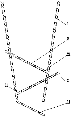
[0007] see figure 1 , the present invention comprises a conical filter cartridge 1, a left inserting plate 2 and a right inserting plate 3, a baffle 11 is provided under the left side plate of the conical filter cartridge 1, and the baffle 11 is arranged on a conical Below the lower opening of the filter cartridge 1, a right notch 21 is provided on the right side of the left board 2, and a left notch 31 is provided on the left side of the right board 3. plate, the right inserting plate 3 is a slanted plate with a low left and a high right, on the left side plate of the conical filter cartridge 1 there is a sloping opening I with a high left and a low right and matching the size of the left inserting plate 2, On the right side plate of the conical filter cartridge 1, there is a slanted opening II with a low left and a high right and is adapted to the size of the right inserting plate 3. The left inserting plate 2 is inserted into the inclined opening I, and the right inserting ...


PUM


Abstract

The invention discloses a flotation machine filter device comprising a conical filter cartridge, a left insertion plate and a right insertion plate, a baffle plate is arranged on the lower side of theleft side plate of the conical filter cartridge, and the baffle plate is arranged below the lower mouth of the conical filter cartridge. A right notch is arranged on the right side of the left insertion plate, a left notch is arranged on the left side of the right insertion plate, the left insertion plate is a sloping board with a higher left side and a lower right side, and the right insertion plate is a sloping board with a lower left side and a higher right side. A slanted mouth I is arranged on the left side plate of the conical filter cartridge, wherein the slanted mouth I is adapted tothe size of the left insertion plate, and has a higher left side and a lower right side, a slanted mouth II is arranged on the right side plate of the conical filter cartridge, wherein the slanted mouth II is adapted to the size of the right insertion plate, and has a lower left side and a higher right side. The left insertion plate is inserted into the slanted mouth I, the right insertion plate is inserted into the slanted mouth II, and the right insertion plate is installed below the left insertion plate. The flotation machine filter device has the advantages of good liquid surface control effect, small liquid level fluctuation, easy cleaning, simple structure, low cost, safety and reliability, and long service life.

Description

technical field [0001] The invention relates to a mine flotation machine, in particular to a filter device for a flotation machine. Background technique [0002] When the existing flotation machine is working, in order to scrape off the useful foam in time, it is necessary to control the liquid level in the flotation tank in real time. The existing liquid level control is adjusted manually by means of visual and sensory control of the gate. Because this method cannot timely and accurately control the liquid level, the adjustment error is relatively large, resulting in a low mining rate. In order to better control the liquid level, an ultrasonic measuring instrument or a laser measuring instrument can be used to measure and control the liquid level. When the machine is working, the liquid level fluctuates greatly, and there are many foams on the liquid surface, which will also lead to large errors in measurement and control. Contents of the invention [0003] The object of...

Claims


Application Information

Patent Timeline
IPC IPC(8): B01D29/11B01D35/02B03D1/14
CPCB01D29/11B01D35/02B03D1/14
Inventor 黄凌志
Owner DAYE XINGYUN ELECTROMECHANICAL TECH RES INST
Learn More