
Programmable delay trigger pulse synchronization device

A technology of delay triggering and synchronizing device, applied in the field of electronics, can solve the problems of complex circuit hardware structure, dependence on trigger pulse synchronization machine, and inability to change the number of output channels, and achieve the effect of simplifying circuit hardware structure and reducing hardware cost.

Inactive Publication Date: 2018-05-08
SHENZHEN INST OF ADVANCED TECH
View PDF5 Cites 10 Cited by
  • Summary
  • Abstract
  • Description
  • Claims
  • Application Information

AI Technical Summary

Problems solved by technology

[0004] The purpose of the present invention is to provide a programmable delay trigger pulse synchronization device, which aims to solve the problem that the trigger pulse synchronization machine in the prior art is completely dependent on the circuit hardware. Once the circuit hardware is finalized, the number of output channels cannot be changed and the output is synchronized. The delay of the pulse signal requires an additional delay chip to achieve, and the circuit hardware structure is complex

Method used


Image

  • Programmable delay trigger pulse synchronization device
  • Programmable delay trigger pulse synchronization device
  • Programmable delay trigger pulse synchronization device

Examples


Embodiment Construction

[0026] In the following description, specific details such as specific system structures and technologies are presented for the purpose of illustration rather than limitation, so as to thoroughly understand the embodiments of the present invention. It will be apparent, however, to one skilled in the art that the invention may be practiced in other embodiments without these specific details. In other instances, detailed descriptions of well-known systems, devices, circuits, and methods are omitted so as not to obscure the description of the present invention with unnecessary detail.

[0027] In order to illustrate the technical solutions of the present invention, specific examples are used below to illustrate.

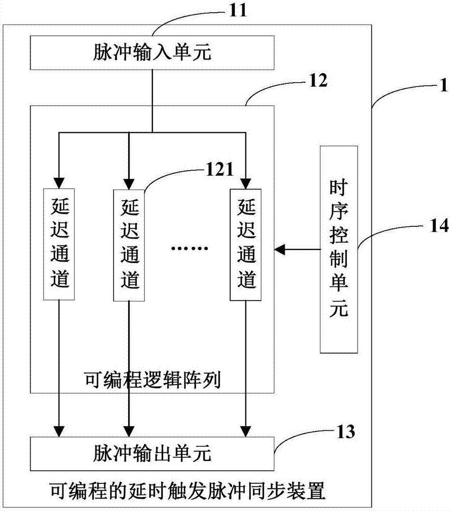
[0028] figure 2 It is a schematic structural diagram of a programmable delay trigger pulse synchronization device provided by an embodiment of the present invention. For ease of description, only parts related to the embodiments of the present invention are shown.

...


PUM


Abstract

The invention is applicable to the technical field of electronics, and provides a programmable delay trigger pulse synchronization device, which comprises a pulse input unit, a programmable logic array, a pulse output unit and a control unit, wherein the pulse input unit is used for inputting multiple paths of pulse signals to the programmable logic array; the programmable logic array is formed bymultiple paths of delay channels, and the multiple paths of delay channels are respectively used for carrying out delayed time processing on the multiple paths of pulse signals in order to output multiple paths of synchronous signals to the pulse output unit; the control unit is used for configuring the number of the delay channels in the programmable logic array and the delay time of each delaychannel; and the pulse output unit is used for outputting the multiple paths of synchronous signals to a lower-level circuit. According to the device, the number of the delay channels and the delay time of each delay channel can be conveniently and flexibly changed, a circuit hardware structure of a synchronous machine is simplified, and the hardware cost of synchronous machine products is reduced.

Description

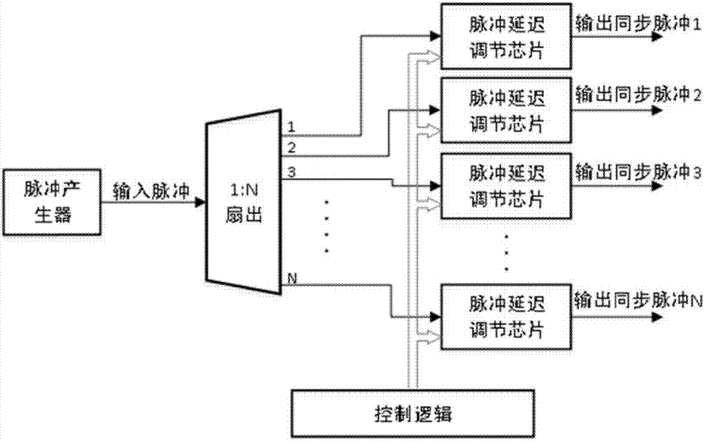
technical field [0001] The invention belongs to the field of electronic technology, in particular to a programmable delay trigger pulse synchronization device. Background technique [0002] In complex large-scale physical implementations or complex instrument systems, there are generally multiple instruments of different types or different individuals of the same type of instruments that need to coordinate their work. The station is delayed for a period of time to work, so it is necessary to trigger the synchronous machine to give synchronous signals respectively, so that these numerous instruments can be coordinated to form an instrument system. [0003] see figure 1 As shown, the existing trigger pulse synchronization technology is realized by combining a 1:N fan-out chip with a discrete delay-adjustable chip, where N is a positive integer, and multi-level cascading of 1:N fan-out is used to realize the expansion of multi-channel signals . This kind of trigger pulse syn...

Claims


Application Information

Patent Timeline
IPC IPC(8): H03K5/15
CPCH03K5/1508
Inventor 桑子儒杨永峰邝忠华王晓辉胡战利任宁赵斌清付鑫吴三梁栋刘新郑海荣
Owner SHENZHEN INST OF ADVANCED TECH
Learn More