
All-optical logic gates using nonlinear elements-claim set V

a logic gate and optical device technology, applied in logic circuits using specific components, instruments, pulse techniques, etc., can solve the problems of requiring very stringent control of the amplitude of the optical signals on which logic operations are performed, the inability to represent logic levels stably for as long as may be required, and the inability to achieve the effect of changing the amount of input power required for switching

Inactive Publication Date: 2008-08-05
COVEY JOHN
View PDF27 Cites 12 Cited by
  • Summary
  • Abstract
  • Description
  • Claims
  • Application Information

AI Technical Summary

Benefits of technology

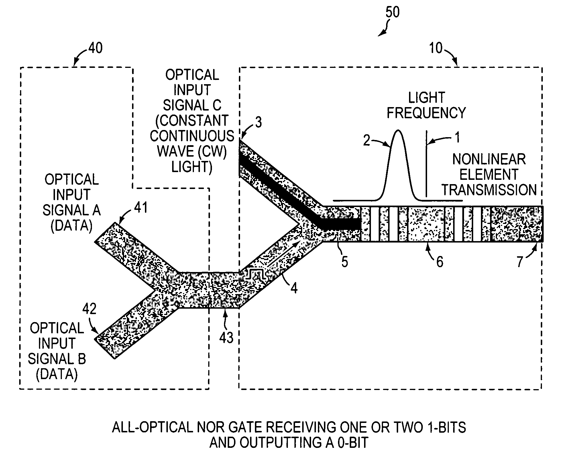
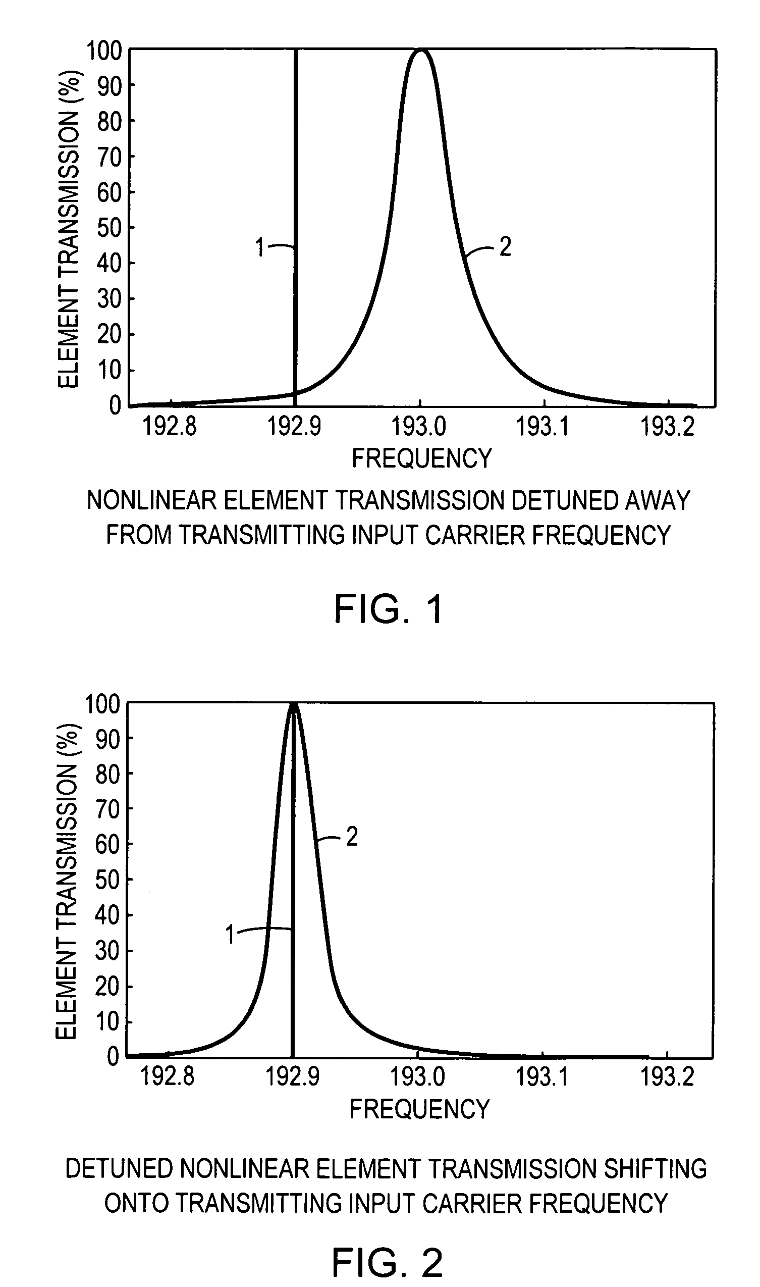
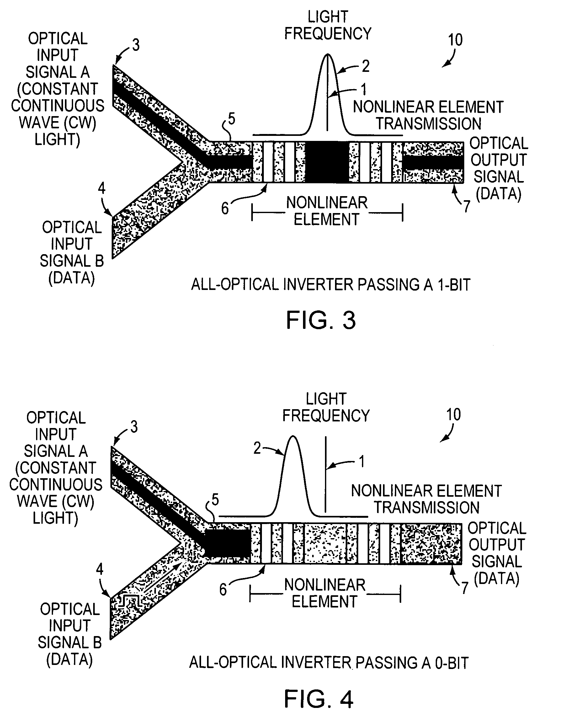
[0016]The nonlinear element acts as a switch responsive to the logic levels of the optical input signals and either switches its output from off to on or from on to off depending on how the nonlinear element is tuned or detuned to the input carrier frequency. Moreover, the amount of input power required to switch can be altered by changing the amount of detuning. By properly arranging the number of inputs and customizing each nonlinear element's unloaded and loaded resonant frequencies, a selected logical function can be implemented without using any electronics at competitive switching speeds. Furthermore, if continuous light is also coupled as one of the optical input signals to a nonlinear element, restoration of optical intensity (i.e. logic level) at each stage of an optical circuit is possible. If the continuous light is used to maintain the nonlinear element at maximum transmission, additional data pulses will shift the nonlinear element out of resonance, which yields all-optical logical inversion. Because all-optical intensity-restorative logic gates are possible, stable all-optical memory is another possible embodiment of this invention.

Problems solved by technology

However, use of optical devices to form integrated logic circuits presents unique challenges.
The ability to represent a logic level stably for as long as may be required becomes an issue.
The problem with such an approach is that it requires very stringent control on the amplitudes of the optical signals on which logic operations are performed.
Thus, the problem of two or more high levels adding becomes more complicated and compounds as logic gates are cascaded.
As signals propagate through optical devices, propagation losses become a significant problem that usually inhibits the cascading of optics.
Moreover, providing gain to optical signals in a densely integrated substrate currently has technological and practical barriers to being achieved.
This behavior has always been considered undesirable, for conventional digital design requires a constant output level regardless of the input level once a threshold is reached.

Method used


Image

  • All-optical logic gates using nonlinear elements-claim set V
  • All-optical logic gates using nonlinear elements-claim set V
  • All-optical logic gates using nonlinear elements-claim set V

Examples


Embodiment Construction

[0041]The present inventions now will be described more fully hereinafter with reference to the accompanying drawings, in which some, but not all embodiments of the invention are shown. Indeed, these inventions may be embodied in many different forms and should not be construed as limited to the embodiments set forth herein; rather, these embodiments are provided so that this disclosure will satisfy applicable legal requirements. Like numbers refer to like elements throughout.

Definitions

[0042]‘Downstream’ refers to a position or element that is further along an optical transmission path relative to a reference point. It can also be used to refer to the direction of travel of light in an optical circuit away from a reference point.

[0043]‘Off’ or ‘low’ or ‘0’ refers to an optical signal having a relatively low amplitude or logic level.

[0044]‘On’ or ‘high’ or ‘1’ refers to an optical signal having a high amplitude or logic level.

[0045]‘Or’ is used in its inclusive sense to mean any one...


PUM

PropertyMeasurementUnit
surface roughnessaaaaaaaaaa

Abstract

An all-optical logic gates comprises a nonlinear element such as an optical resonator configured to receive optical input signals, at least one of which is amplitude-modulated to include data. The nonlinear element is configured in relation to the carrier frequency of the optical input signals to perform a logic operation based on the resonant frequency of the nonlinear element in relation to the carrier frequency. Based on the optical input signals, the nonlinear element generates an optical output signal having a binary logic level. A combining medium can be used to combine the optical input signals for discrimination by the nonlinear element to generate the optical output signal. Various embodiments include all-optical AND, NOT, NAND, NOR, OR, XOR, and XNOR gates and memory latch.

Description

BACKGROUND OF THE INVENTION[0001]1. Field of the Invention[0002]This invention relates to optical devices functioning as all-optical logic gates. More specifically, digital optical signals are combined and provided to nonlinear elements such as optical resonators or cavity switches whose resonance frequencies are tuned to produce desired logic output signals.[0003]2. Description of the Related Art[0004]In electronic devices, logic gates composed of transistors comprise the basic elements of digital circuits. Voltage-based inputs are received by the gates, resulting in voltage-based output signals corresponding to the desired logical function.[0005]Interest has begun to emerge in recent years toward development of an optical device that behaves analogously to electronic logic gates. The reason for this interest is that optical signals can potentially travel faster in integrated circuits than electrical signals because they are not subject to capacitance which slows switching speed be...

Claims


Application Information

Patent Timeline
Patent Type & Authority Patents(United States)
IPC IPC(8): G02B6/00G02B6/10G02F3/00
CPCG02F3/024G02F2203/15G02F2202/32
Inventor COVEY, JOHN LUTHER
Owner COVEY JOHN
Learn More