Built-in permanent magnet synchronous motor for kart

A permanent magnet synchronous motor, built-in technology, applied to synchronous machines, synchronous motors with stationary armatures and rotating magnets, synchronous machine parts, etc., can solve the problem of high torque fluctuation standards and poor rotor structure design Reasonable, weaken the motor torque fluctuation and other problems, to achieve the effect of optimizing the working characteristics, reducing weight and reducing torque ripple

Inactive Publication Date: 2018-05-08
株洲罗伯特电机有限公司
View PDF3 Cites 3 Cited by
  • Summary
  • Abstract
  • Description
  • Claims
  • Application Information

AI Technical Summary

Problems solved by technology

[0004] Permanent magnet synchronous motors have a series of advantages such as simple structure, low loss, high power factor, and high efficiency. However, permanent magnet synchronous motors have some defects, such as torque fluctuations, which will affect the control accuracy of the system and cause vibration and noise. High places, the torque fluctuation standard requirements are higher
In order to weaken the torque fluctuation of the motor, in terms of the design of the motor body, the existing surface-mounted permanent magnet motor rotors generally use unequal-thickness magnet steel, or split oblique poles or inclined slots; and for the built-in rotor structure, due to the magnetic circuit The large leakage flux of the magnetic steel makes the utilization rate of the magnetic steel low, and the unreasonable design of the rotor structure often results in poor overload capacity of the motor, low power density, high stray loss and rotor eddy current loss, etc.

Method used


Image

  • Built-in permanent magnet synchronous motor for kart
  • Built-in permanent magnet synchronous motor for kart
  • Built-in permanent magnet synchronous motor for kart

Examples


Embodiment

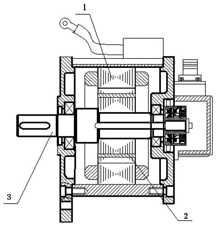
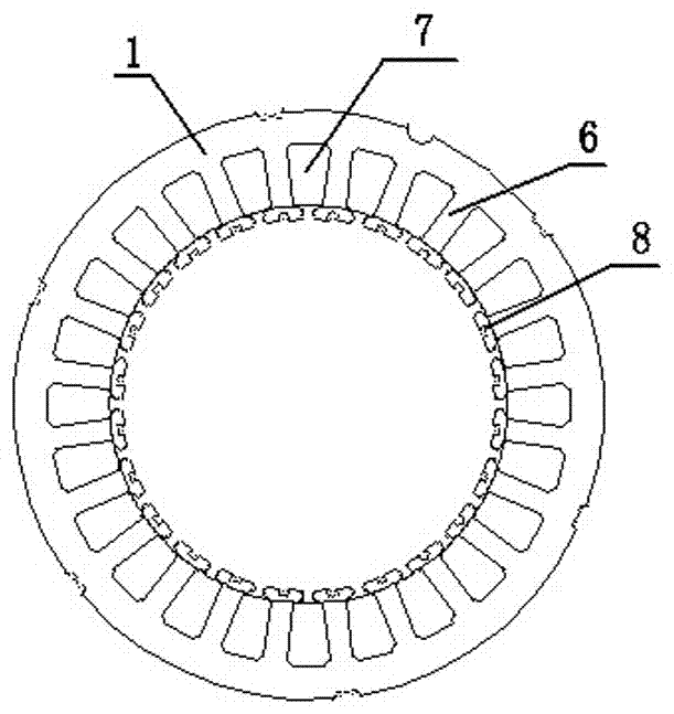
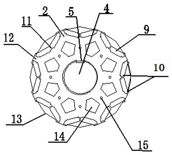
[0032] Such as Figure 1~3 A built-in permanent magnet synchronous motor for karts is shown, including a stator core, a rotor core and a rotor shaft. The stator core is sleeved on the outside of the rotor core, and the rotor core is sleeved on the outside of the rotor shaft. The stator core It is made of laminated silicon steel sheets, and the rotor core is made of laminated silicon steel sheets; the rotor core includes a shaft hole in the center, and the side wall of the shaft hole is provided with a keyway matching the rotor shaft flat key. The stator core is equipped with 24 stator teeth, and stator slots are formed between adjacent stator teeth. The stator teeth and stator slots have a symmetrical structure in the radial direction. The end of the stator teeth facing the rotor is the tooth end of the stator teeth, and the stator teeth The central part of the tooth end is provided with an arched virtual groove. The rotor iron core is provided with 4 opposite V-shaped magnet...


PUM


Abstract

The invention relates to a built-in permanent magnet synchronous motor for a kart. The built-in permanent magnet synchronous motor for a kart includes a stator core, a rotor core and a rotor spindle,wherein the stator core is provided with a plurality of stator teeth; a stator groove is formed between every adjacent stator teeth; the tooth end of each stator teeth is provided with an arc elementary slot; a plurality of V type magnetic poles facing the outer peripheral face of the rotor are arranged on the rotor core in the circumferential direction; each pair of V type magnetic poles are symmetrically arranged by taking the symmetrical center line between the pair of magnetic poles as the axle; an intra-polar magnetism isolating bridge and an inter-polar magnetism isolating bridge of eachV type magnetic pole are the same in the width; the external diameter of the rotor core includes eccentric arcs corresponding to the V type magnetic poles; an eccentric distance is arranged between the center of circle of each eccentric arc and the center of circle of the rotor spindle, and the eccentric distance between the center of circle of each eccentric arc and the center of circle of the rotor spindle is the same; the rotor core is provided with a plurality of ventilating holes corresponding to each pair of V type magnetic poles; the rotor core is provided with a plurality of rivet holes which are arranged between the V type magnetic poles and the rotor spindle and are distributed along a ring shape.

Description

technical field [0001] The invention relates to the field of permanent magnet synchronous motors, in particular to a built-in permanent magnet synchronous motor for karts. Background technique [0002] Permanent magnet motors have the characteristics of high power density, high efficiency, and high reliability, and have been widely used in industrial production and household life. At present, in the cost of permanent magnet motors, permanent magnet materials occupy a large proportion, which causes the competitiveness of permanent magnet motors in low-end applications to decline. In order to improve the utilization rate of permanent magnets and the price competitiveness of permanent magnet motors, optimizing the structure of permanent magnet motors to improve their power and torque density has become an important research topic for experts and scholars at home and abroad. [0003] The interior permanent magnet motor is a synthesis of permanent magnet torque and reluctance to...

Claims


Application Information

Patent Timeline
Patent Type & Authority Applications(China)
IPC IPC(8): H02K21/16H02K21/02H02K1/14H02K1/32H02K1/27
CPCH02K21/16H02K1/14H02K1/276H02K1/32H02K21/028H02K2213/03
Inventor 黄建军杨勇
Owner 株洲罗伯特电机有限公司
Why Eureka
Try Eureka