
Material level prediction method for ball mill

A prediction method and ball mill technology, applied in computer parts, special data processing applications, complex mathematical operations, etc., can solve the problems of low material level recognition efficiency, error in inference results, drift of load control points, etc., and achieve good practical value. and promotion prospects, high accuracy, and small fluctuations

Active Publication Date: 2018-05-08
TAIYUAN UNIV OF TECH
View PDF12 Cites 4 Cited by
  • Summary
  • Abstract
  • Description
  • Claims
  • Application Information

AI Technical Summary

Problems solved by technology

From trial and error, we found that a single signal source has certain limitations. For example: the continuous increase in the use time of the piezoelectric signal, the piezoelectric strain sensor is prone to zero drift, resulting in a decrease in measurement accuracy; the differential pressure signal requires more auxiliary variables. , each variable value is difficult to obtain accurately, there is redundancy and coupling between variables, and the system complexity is high, which is inconvenient to maintain; the vibro-acoustic signal is easily interfered by the noise from the adjacent mill, so that the material level recognition efficiency is not good High; the vibration signal is easily affected by factors such as the power grid and the loss of the grinding body in the mill, so that the load control point drifts; the power signal is greatly affected by the current, and the current is affected by the wear of the steel balls and the reduction of the total amount of steel balls. , changes in coal quality, and changes in air volume, so there are large errors in the inference results

Method used


Image

  • Material level prediction method for ball mill
  • Material level prediction method for ball mill
  • Material level prediction method for ball mill

Examples


Embodiment Construction

[0029] The technical solution of the present invention will be further described in more detail below in conjunction with specific embodiments. Apparently, the described embodiments are only some, not all, embodiments of the present invention. Based on the embodiments of the present invention, all other embodiments obtained by persons of ordinary skill in the art without creative efforts shall fall within the protection scope of the present invention.

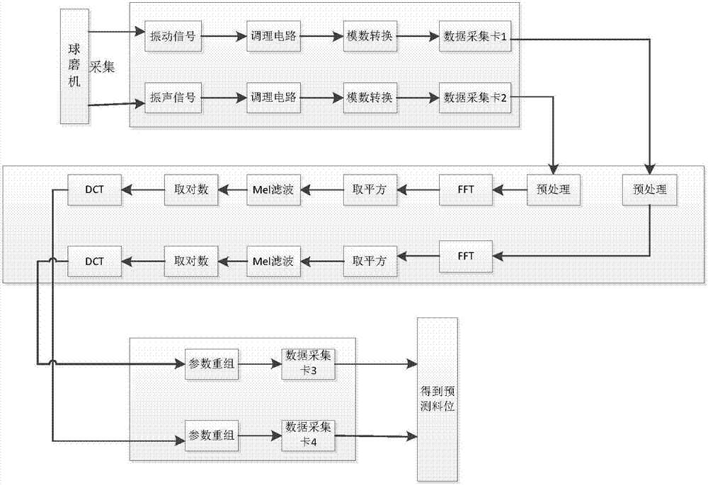
[0030] refer to figure 1 , figure 1 It is a schematic flow chart of a ball mill material level prediction method provided by the present invention. The steps of the method include:

[0031] S110: Fill the ball mill drum with materials, and collect vibration signals of the ball mill at different material levels X s and vibration signal X v .

[0032] The method of the present invention involves two theoretical methods of MFCC and TBM. MFCC is a method to extract sound features. It is robust and can be used to analyze nonli...


PUM


Abstract

The invention discloses a material level prediction method for a ball mill. The method comprises the following steps that: collecting a vibration signal on the cylinder wall or the bearing of the ballmill and the sound vibration signals of microphones around the ball mill; inputting the vibration signal and a sound vibration signal into a data collection card through a conditioning circuit and ananalog-to-digital conversion circuit; through an MFCC (Mel-Frequency Cepstral Coefficients, independently calculating the feature parameters of the vibration signal and the sound vibration signal inthe data collection card; re-combining the vibration signal with the sound vibration signal; collecting the re-recombined signal by the data collection card; and finally, predicting the material levelof a corresponding signal for data in the data collection card through a TBM (Tactical Ballistic Missile) model established by historical data. By use of the method, the material level of the ball mill can be effectively predicted, and the method has the advantages of high material level prediction accuracy, small fluctuation and good practical value and popularization prospect.

Description

technical field [0001] The invention relates to the field of data detection, in particular to a ball mill material level prediction method. Background technique [0002] Roller ball mill is a basic milling equipment. The material level inside the ball mill drum is the key factor affecting the energy consumption, production efficiency and production safety of the ball mill. Accurate prediction makes the ball mill system difficult to operate economically and prone to safety accidents. Therefore, it is of great significance to effectively predict the material level of the ball mill for the efficient, safe and stable operation of the ball mill system. [0003] At present, the ball mill material level measurement method based on soft sensor mainly predicts the material level through a single signal source such as piezoelectric signal, differential pressure signal, vibroacoustic signal, vibration signal or power signal. From trial and error, we found that a single signal source...

Claims


Application Information

Patent Timeline
IPC IPC(8): G06K9/00G06F17/14
CPCG06F17/147G06F2218/02G06F2218/08
Inventor 庞宇松李国勇李思思闫飞阎高伟
Owner TAIYUAN UNIV OF TECH
Learn More