
Grain dryer

A grain dryer and drying bin technology, applied in dryers, drying, local stirring dryers, etc., can solve the problems of affecting grain, grain mildew and deterioration, poor drying efficiency, etc., and reduce heat loss Effect

Inactive Publication Date: 2018-05-08
泰州市乐律金属制品有限公司
View PDF0 Cites 3 Cited by
  • Summary
  • Abstract
  • Description
  • Claims
  • Application Information

AI Technical Summary

Problems solved by technology

[0002] Grain is one of the common staple foods in people's life, and the demand is predictable, so grain reserves are indispensable, but the grain that has just been harvested is not suitable for storage. Excessive moisture in the grain will not only accelerate the growth of grain mold Deterioration will also increase the moisture content of the air in the storage warehouse, affecting the grain that has been stored in the warehouse, causing it to be damp and deteriorating, which will cause potential harm to the health of the eater. Therefore, a drying process is required before the grain is put into the warehouse to ensure the quality of the grain. and safe storage. Although the traditional method of natural drying in the sun is simple and the cost is not high, it will not only lead to different quality due to natural factors, but also the storage time will become uncertain due to bad weather. Drying requires a large space and there are many uncertain factors. Although the existing machine drying method can accurately control the moisture content of the grain and has fewer uncertain factors, it has high cost and poor drying efficiency.

Method used


Image

  • Grain dryer

Examples


Embodiment Construction

[0012] The preferred embodiments of the present invention are given below in conjunction with the accompanying drawings to describe the technical solution of the present invention in detail.

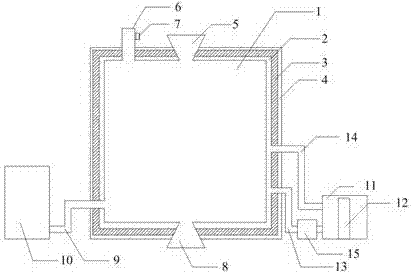
[0013] A grain dryer, characterized in that it comprises: a drying chamber 1 wrapping a cavity 2, the cavity 2 wrapping an insulation layer 3, the insulation layer 3 wrapping a casing 4, and the inlet 5 and the air outlet 6 are installed On the top of the drying bin 1, the air outlet 6 is installed on the left side of the inlet 5, and the middle of the bottom of the drying bin 1 is provided with a discharge port 8. The hot air blower 10 is connected to the side of the drying bin 1 through the hot air channel 9, and the water tank 11 The water pump 15 is installed on the delivery channel 13, the heater 12 is installed in the water tank 11, and the water in the water tank 11 is heated by the heater 12 and then used The water pump 15 is injected into the cavity 2 from the delivery channel 1...


PUM


Abstract

The invention discloses a grain dryer. The grain dryer is characterized by comprising that the exterior of a drying bin is wrapped by a cavity; the exterior of the cavity is wrapped by a heat preserving layer; the exterior of the heat preserving layer is wrapped by a shell; a feeding port and an air outlet are formed in the upper portion the drying bin; the air outlet is installed on the left sideof the feeding port; the middle of the lower portion of the drying bin is provided with a discharging port; a hot air blower is connected to one side of the drying bin through a hot air channel; a water tank is connected to one side of a water heating layer through a conveying channel and a recycling channel; a water pump is installed on the conveying channel; a heater is installed in the water tank; and a valve is installed on the outer side of the air outlet. According to the grain dryer, on the premise that control over the water of dried grain is guaranteed, hot water is injected into thecavity to rise the temperature in the bin, and the hot air blower is used for accelerating flowing of air on the surface of grain under the condition that the temperature in the bin is not affected to increase the drying speed; the exterior of the drying bin is wrapped by the heat preserving layer so that the heat loss can be reduced; the controllable air outlet is installed in the upper portionthe drying bin, the size of the air outlet is controlled to adjust flowing of air in the drying bin, and a function of controlling the water of the grain is achieved.

Description

technical field [0001] The invention relates to a dryer, in particular to a grain dryer. Background technique [0002] Grain is one of the common staple foods in people's life, and the demand is predictable, so grain reserves are indispensable, but the grain that has just been harvested is not suitable for storage. Excessive moisture in the grain will not only accelerate the growth of grain mold Deterioration will also increase the moisture content of the air in the storage warehouse, affecting the grain that has been stored in the warehouse, causing it to be damp and deteriorating, which will cause potential harm to the health of the eater. Therefore, a drying process is required before the grain is put into the warehouse to ensure the quality of the grain. and safe storage. Although the traditional method of natural drying in the sun is simple and the cost is not high, it will not only lead to different quality due to natural factors, but also the storage time will become ...

Claims


Application Information

Patent Timeline
Patent Type & Authority Applications(China)
IPC IPC(8): F26B9/06F26B21/00F26B25/12A23B9/08
CPCF26B9/06A23B9/08F26B21/001F26B25/12F26B2200/06
Inventor 张美红
Owner 泰州市乐律金属制品有限公司
Learn More