Self-cleaning structure of range hood

A range hood and self-cleaning technology, which is applied in the field of self-cleaning, can solve the problems of unable to clean the volute, reduce the temperature of the volute, and uneven cleaning effect, and achieve good cleaning effect and increase the temperature

Pending Publication Date: 2018-05-08
NINGBO FOTILE KITCHEN WARE CO LTD
View PDF2 Cites 2 Cited by
  • Summary
  • Abstract
  • Description
  • Claims
  • Application Information

AI Technical Summary

Problems solved by technology

[0004] (1) When the motor is inching, the impeller rotates too fast, which will suck away the high-temperature steam in the volute, reducing the internal temperature of the volute, which is not conducive to the melting of grease;
[0005] (2) When the speed of the impeller is too fast, the time for the steam to continuously act on a certain area of ​​the impeller will be correspondingly shortened, which will weaken the washing effect of the steam and affect the cleaning effect;
[0006] (3) The steam from the nozzle can only be sprayed and cleaned against a certain part of the volute, and cannot clean the entire inner surface of the volute, resulting in uneven cleaning effect

Method used


Image

  • Self-cleaning structure of range hood
  • Self-cleaning structure of range hood
  • Self-cleaning structure of range hood

Examples


Embodiment 1

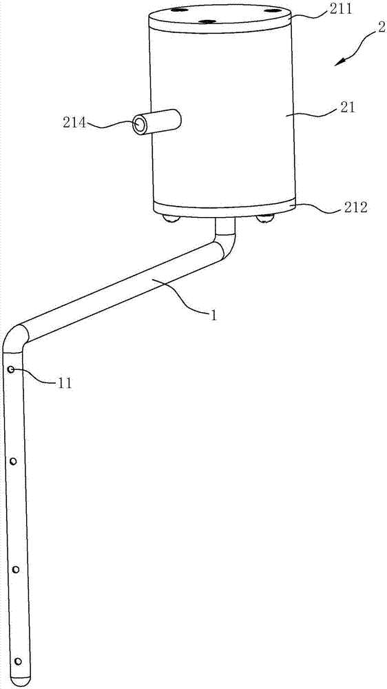
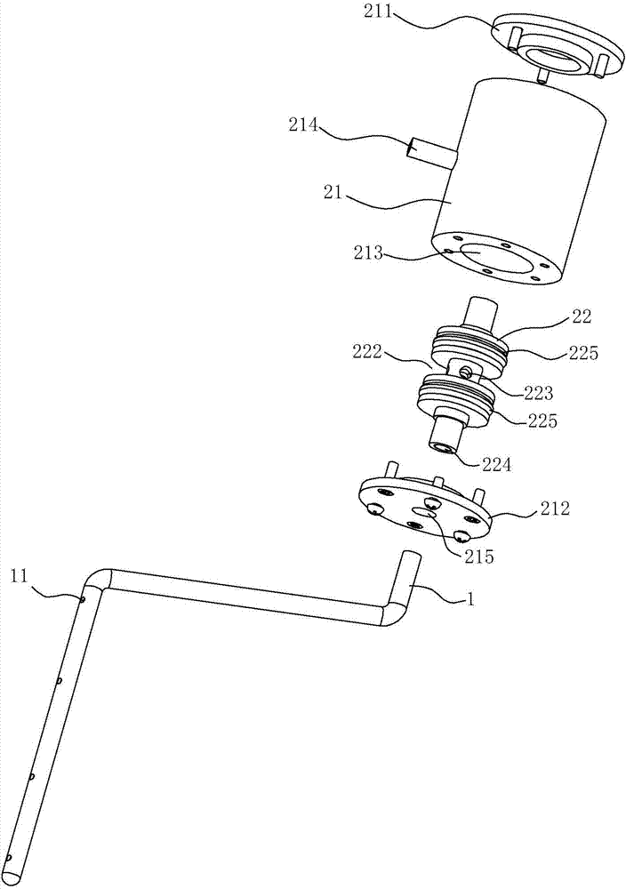
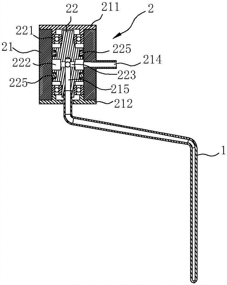
[0029] Such as Figure 1~4 As shown, the self-cleaning structure of the range hood in this embodiment includes a steam nozzle 1 and a driving structure 2 , both of which are arranged on the impeller 3 , and the impeller 3 is arranged in the volute 4 .

[0030] In this embodiment, the volute 4 is provided with an air inlet 41 of the impeller 3, and a mesh ring 42 is installed on the air inlet 41, and the driving structure 2 is fixed on the outside of the mesh ring 42 by screws, and one end of the steam nozzle 1 is connected to the driving The structure 2 is connected, the other end of the steam nozzle 1 extends into the impeller 3 through the mesh ring 42, and the middle part of the steam nozzle 1 extends toward the blade of the impeller 3, and the lower part of the steam nozzle 1 extends along the length direction of the blade of the impeller 3 Arranged, when the steam nozzle 1 rotates, it can form a circular movement track in the inner peripheral space of the impeller 3 .

...

Embodiment 2

[0036] The difference between this embodiment and embodiment 1 is only: as Figure 5As shown, the driving structure 2 of this embodiment also includes a motor 23 , the motor 23 is arranged on the top of the sleeve 21 and the output shaft 231 extends into the sleeve 21 and is connected with the upper end of the connecting member 22 . Specifically, the first end cap 211 on the top of the sleeve 21 is provided with an opening 216 through which the output shaft 231 of the power supply motor 23 passes, and the upper end of the connector 22 extends upwards to form a connecting portion 226, which is connected to the motor 23. The output shaft 231 is connected through a coupling 232 .

[0037] After the motor 23 is added in this embodiment, the motor 23 can be used to drive the connector 22 to drive the steam nozzle 1 to rotate, which is beneficial to control the speed of the steam nozzle 1 and achieve a better steam cleaning effect.


PUM


Abstract

The invention relates to a self-cleaning structure of a range hood. The self-cleaning structure of the range hood comprises a steam spraying pipe arranged on an impeller of the range hood, and a driving structure capable of rotating the steam spraying pipe relative to the impeller; the driving structure is arranged in an intake port of the impeller, and is connected with a first end of the steam spraying pipe; a second end of the steam spraying pipe extends into the impeller, and can form an annular motion trajectory in inner periphery space of the impeller; a second end of the steam sprayingpipe is closed; and a nozzle for spraying out steam is formed in the side wall. The driving structure is not needed to provide power to the steam spraying pipe, but is only needed to enable the firstend of the steam spraying pipe to conveniently introduce air and to achieve free rotation; when steam is sprayed from the steam spraying pipe to blades of the impeller, as the blades have a certain radian, the blades can apply reactive force to the steam spraying pipe through steam to push rotation of the steam spraying pipe; and the rotating speed of the steam spraying pipe is lower, and the timeof the steam continuously acting on one local area of the impeller is longer, so that effective scouring of the impeller by the steam is facilitated, and better cleaning effect is achieved.

Description

technical field [0001] The invention relates to the technical field of self-cleaning of a range hood, in particular to a self-cleaning structure of an impeller of a range hood. Background technique [0002] During the use of the range hood, a large amount of oil will accumulate on the impeller and the filter, which will easily cause blockage, increase the load, etc., and affect the use effect of the range hood. With the continuous advancement of range hood self-cleaning technology, steam cleaning has been widely used in the self-cleaning field of range hoods. The basic principle of steam cleaning is to generate steam from a steam generator, and then deliver the steam to the nozzle at the end of the spray pipe. The steam is quickly ejected from the nozzle to wash the impeller and the volute for cleaning. [0003] For example, the Chinese invention patent application with application publication number CN104421988A "Steam generator, cleaning system and range hood" (applicatio...

Claims


Application Information

Patent Timeline
Patent Type & Authority Applications(China)
IPC IPC(8): F24C15/20B08B3/02
CPCF24C15/20B08B3/02
Inventor 贺峰胡涛茅忠群诸永定李斌
Owner NINGBO FOTILE KITCHEN WARE CO LTD
Why Eureka
Try Eureka