Eureka AIR delivers breakthrough ideas for toughest innovation challenges, trusted by R&D personnel around the world.

Water stop clamping tool, tunnel longitudinal water stop structure and construction method

A longitudinal water-stop and water-stop technology, used in tunnels, tunnel linings, and earth-moving drilling, etc., can solve the problems of water-stop parts distortion, difficult positioning, serious distortion, etc., to ensure the water-stop effect, achieve accurate positioning, The effect of ensuring project safety

Active Publication Date: 2018-05-08
CHINA RAILWAY ERJU 5TH ENG +1
View PDF5 Cites 4 Cited by
  • Summary
  • Abstract
  • Description
  • Claims
  • Application Information

AI Technical Summary

Problems solved by technology

[0009] The purpose of the present invention is to solve the problems of difficult positioning, severe distortion and inconvenient splicing when waterproof woven fabric or waterproof rubber strip is used as the longitudinal water-stop structure of the tunnel in the prior art, which leads to poor longitudinal water-stop effect of the tunnel and easy occurrence of water seepage In order to solve the problems that affect the quality and safety of the project, a waterstop fixture, a tunnel longitudinal waterstop structure and a construction method are provided. The water-stop parts are clamped and fixed, and the position of the water-stop parts is effectively adjusted through the connecting part, thus solving the problem of difficult positioning. At the same time, changing the water-stop parts solves the serious distortion and inconvenient splicing of the existing water-stop parts To solve the problem, the water-stop parts can be firmly fixed by the water-stop clamp, so as to achieve the purpose of accurate positioning, straightness without distortion and convenient connection of the water-stop parts, so as to ensure the engineering quality and engineering safety of the tunnel waterproof construction

Method used


Image

  • Water stop clamping tool, tunnel longitudinal water stop structure and construction method
  • Water stop clamping tool, tunnel longitudinal water stop structure and construction method
  • Water stop clamping tool, tunnel longitudinal water stop structure and construction method

Examples


Embodiment 1

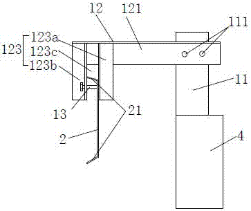
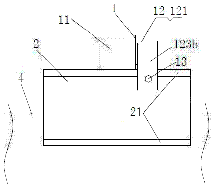
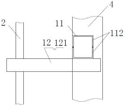
[0062] Such as figure 1 , figure 2 , image 3 with Image 6 As shown, the waterstop clamp 1 includes a fixing part 11 for being installed on the tunnel side wall template 4, and a connecting part 12 connected with the fixing part 11 and extending to the top of the concrete pouring area 6, the The connection part 12 is provided with a mounting structure 13 for connecting the water stop belt 2, and the relative position between the water stop belt 2 and the connection part 12 can be adjusted, so that after the water stop belt 2 is connected to the connection part 12, the The water stop 2 corresponds to the construction joint 3, and the water stop 2 is a metal plate water stop.

[0063] Further, the formwork for the side wall of the tunnel is an inverted trestle side formwork. During the construction process of the inverted arch trestle, the waterstop clamp is installed on the side formwork of the inverted arch trestle, which has the advantages of convenient installation and ...

Embodiment 2

[0072] Such as Figure 4 with Figure 5 As shown, the waterstop clamp of this embodiment is the same as that of Embodiment 1, only the structure of the connecting portion 12 is different.

[0073] The connecting part 12 includes a crossbeam 121 connected with the fixing part 11, the crossbeam 121 is arranged substantially horizontally, the end of the crossbeam 121 is connected with a longitudinal beam 122, and the longitudinal beam 122 is substantially vertically arranged, and the installation structure 13 is set on The vertical strip holes on the longitudinal beams 122 are provided with fasteners 13A for installing the waterstop 2 on the longitudinal beams 122. strip holes, so that after the waterstop 2 is installed on the longitudinal beam 122, it can move up and down along the vertical strip holes, so as to realize the position adjustment of the waterstop 2 in the vertical direction and complete the positioning of the waterstop.

[0074] Further, the beams 121 and the lon...

Embodiment 3

[0076] Such as Image 6 with Figure 7 As shown, the tunnel longitudinal waterstop structure includes a metal plate-shaped waterstop 2 arranged along the longitudinal direction of the tunnel, and a plurality of waterstops as in Example 1 are arranged along the length direction of the metal plate-shaped waterstop 2 Fixture 1, the waterstop fixture 1 is installed on the tunnel side wall template 4, the centerline of the metal plate waterstop 2 roughly coincides with the centerline of the construction joint 3, and the metal plate waterstop 2 is installed The radial position allows a deviation of ±50mm, and the longitudinal direction allows deviation from the center to be ±30mm.

[0077] The longitudinal water-stop structure of the tunnel adopted in this scheme makes the construction joints have a good waterproof effect without water seepage. The radial position of the metal plate water-stop installation refers to the horizontal position of the water-stop, while the metal plate ...


PUM


Abstract

The invention relates to the technical field of tunnel construction, in particular to a water stop clamping tool, a tunnel longitudinal water stop structure and a construction method. The water stop clamping tool comprisesa fixing part for mounting on a tunnel side wall template, and a connecting part connected with the fixing part and extending to be above a concrete pouring area; the connectingpart is provided with a mounting structure for connecting with a metal-plate-shaped water stop, and the relative position between the water stop and the connecting part can be adjusted, so that the water stop corresponds to a construction joint after the water stop is connected with the connecting part. The water stop clamping tool is arranged on an inverted arch trestle template, water stop partsare fixed by the connecting part, and the effective adjustment is carried out through the connecting part, thereby solving the problem of difficulty in positioning; and the water stop parts are changed to solve the problems of severe distortion and inconvenience in splicing of the existing water stop parts and achieve the purposes of accurate positioning, straightness and no distortion, and convenient connection of the water stop parts, and the construction quality and the construction safety of the tunnel waterproof construction are ensured.

Description

technical field [0001] The invention relates to the technical field of tunnel construction, in particular to a waterstop fixture, a tunnel longitudinal waterstop structure and a construction method. Background technique [0002] In the process of tunnel construction, tunnel waterproof construction is a very important link. If the waterproof construction process is not done well, not only during the tunnel construction process, but also after the tunnel is put into use later, there will be problems of water seepage and waterlogging, which will seriously affect the engineering quality of the tunnel. [0003] The water seepage problem of the tunnel mainly occurs at the construction joints. During the gradual pouring process of the side walls of the tunnel from bottom to top, there will be horizontal transverse joints. The transverse joints extend along the longitudinal direction of the tunnel and their length is The length of the pouring section, in order to avoid water seepag...

Claims


Application Information

Patent Timeline
Patent Type & Authority Applications(China)
IPC IPC(8): E21D11/38
CPCE21D11/38
Inventor 王勇王俊谢亮杨明黄翼姜杨胡威唐磊王浩
Owner CHINA RAILWAY ERJU 5TH ENG
Why Eureka
Eureka Blog
Learn More