Pressing limiting device and method for slab ballastless track structure

A slab ballastless track and limiting device technology, applied in tracks, roads, ballast layers, etc., can solve the problems of the gap between the track slab and the filling layer, the impact of the track structure, and the limited pull-out strength, etc. Plate warpage, high safety and stability, and the effect of preventing relative displacement

Active Publication Date: 2018-05-08
沪杭铁路客运专线股份有限公司 +3
View PDF10 Cites 14 Cited by
  • Summary
  • Abstract
  • Description
  • Claims
  • Application Information

AI Technical Summary

Problems solved by technology

[0003] The slab ballastless track structure is composed of rails, fasteners, track slabs, filling layers, support layers or base plates from top to bottom. When the temperature difference between the track slab is large, warpage of the four corners of the track slab will occur, causing defects such as separation between the track slab and the filling layer. In severe cases, the bond between the track slab and the filling layer will fail, affecting the safe operation of the train. In the event of arching and warping, the existing method is to implant a large number of steel bars between the track slab, filling layer and supporting layer, so that the layered structure is connected in series, but this method changes the layered structure of the ballastless track structure. The force structure has a great impact on the track structure, and the implanted steel bars are not easy to remove, which brings many difficulties to the subsequent track slab replacement and filling layer maintenance
CN104389249 A and CN206553829 U have respectively proposed a kind of detachable high-speed railway ballastless track slab sequestration limiter, these two kinds of devices all have vertical compression and lateral limiter function, the bottom of two kinds of devices are plane However, there are two problems in these two methods. On the one hand, in order to meet the needs of drainage, the concrete support layer is usually designed as an inclined surface, and the compression limit device is directly installed on the On the inclined surface, after installing the compression limit device, the problem that the compression head and the track plate cannot be vertically connected closely; The supporting layer is closely attached, which seriously weakens the limiting force provided by the compression limit device. What is more serious is that the design compressive strength of the supporting layer concrete is C15, which is low in strength, and the reinforcement is directly planted in the supporting layer. The pullout strength is limited, and it is difficult to provide sufficient stability. Therefore, in view of the problem that the surface of the support layer is an inclined surface and the compression limit device is difficult to stick closely, the present invention proposes to set a perfusion bag at the bottom of the compression limit device, and pour the self-leveling Leveling with non-shrinking resin to ensure that there is no gap under the compression limit device; in view of the problem that the support layer has limited strength and it is difficult to provide sufficient pull-out strength, the invention proposes the use of low-viscosity permeable rebar-planting glue for rebar planting The technical solution of anchoring, the present invention is mainly aimed at the structural characteristics of the slab-type ballastless track in the subgrade section, and designs a set of small, light, convenient disassembly, a reasonable combination of vertical stiffness and transverse stiffness, high foundation stability, and strong pull-out resistance. Compression limit device and method for layered slab ballastless track structure of operating lines

Method used


Image

  • Pressing limiting device and method for slab ballastless track structure
  • Pressing limiting device and method for slab ballastless track structure
  • Pressing limiting device and method for slab ballastless track structure

Examples


Embodiment 1

[0036] Embodiment 1: A compression limiting device and method for preventing the arching disease of the slab ballastless track structure

[0037] Consists of the following steps:

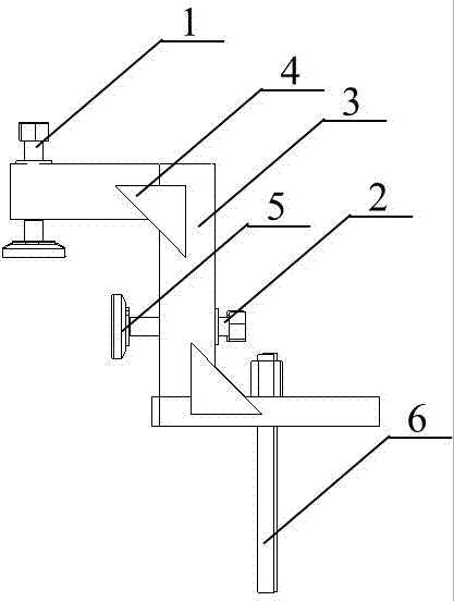
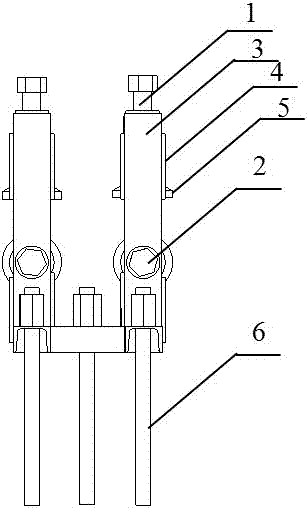
[0038] Step 1: Arrange the compression limit device on the concrete support layer exposed outside the ballastless track slab. The compression limit device is evenly and symmetrically distributed on the line, and the mark corresponds to the planting position of each compression limit device. Twist drill drilling, the drilling diameter is 27mm, the drilling depth is 200mm~250mm, the diameter of the implanted threaded steel bar is 25mm, the length of the threaded steel bar is 320mm, the implantation depth is 200mm, and the permeable planting glue is poured into the drilled hole , the amount of pouring is half of the drilling depth, the planting glue is gradually penetrated into the concrete of the supporting layer, the threaded steel bar is put into the drilling hole, and the air around the steel bar i...

Embodiment 2

[0043] Embodiment 2: A compression limiting device and method for preventing warpage of slab ballastless track structure

[0044] Consists of the following steps:

[0045] Step 1: Arrange the compression limit device on the concrete support layer exposed outside the ballastless track slab. The compression limit device is evenly and symmetrically distributed on the line, and the mark corresponds to the planting position of each compression limit device. Twist drill drilling, the drilling diameter is 27mm, the drilling depth is 200mm~250mm, the diameter of the implanted threaded steel bar is 25mm, the length of the threaded steel bar is 320mm, the implantation depth is 200mm, and the permeable planting glue is poured into the drilled hole , the amount of pouring is half of the drilling depth, the planting glue is gradually penetrated into the concrete of the supporting layer, the threaded steel bar is put into the drilling hole, and the air around the steel bar is discharged in ...

Embodiment 3

[0050] Embodiment 3: A compression limit device and method for lateral deviation correction operation of slab ballastless track structure

[0051] Consists of the following steps:

[0052] Step 1: Arrange the compression limit device on the concrete support layer exposed outside the ballastless track slab. The compression limit device is evenly and symmetrically distributed on the line, and the mark corresponds to the planting position of each compression limit device. Twist drill drilling, the drilling diameter is 27mm, the drilling depth is 200mm~250mm, the diameter of the implanted threaded steel bar is 25mm, the length of the threaded steel bar is 320mm, the implantation depth is 200mm, and the permeable planting glue is poured into the drilled hole , the amount of pouring is half of the drilling depth, the planting glue is gradually penetrated into the concrete of the supporting layer, the threaded steel bar is put into the drilling hole, and the air around the steel bar ...


PUM


Abstract

The invention discloses a pressing limiting device and method for a slab ballastless track structure, which are used for solving problems of upwarp and warping diseases of the slab ballastless track structure of an operating line, realizing synchronous and integral deviation rectification of the laminated slab ballastless track structure and avoiding the dislocation of the laminated structure andupwarp secondary disease of a track slab in the deviation rectifying process.

Description

technical field [0001] The invention belongs to the technical field of maintenance and repair of ballastless track structures of high-speed railways, and relates to a compression limiting device and method used in the operation process and maintenance process of high-speed railway ballastless track. The device and method can ensure the characteristics of layered structure The stability of the slab ballastless track structure can avoid the problems of arching and warping, and it can be applied to CRTS Ⅰ, Ⅱ, Ⅲ slab ballastless track structures. Background technique [0002] The slab ballastless track structure has the characteristics of high production efficiency, high construction precision, and stable construction quality. It is the main track structure form adopted by my country's high-speed railways. Among the high-speed railways that have been put into operation, the slab ballastless track structure accounts for nearly 60% , the slab ballastless track structure also has a ...

Claims


Application Information

Patent Timeline
Patent Type & Authority Applications(China)
IPC IPC(8): E01B1/00E01B26/00
CPCE01B1/002E01B26/00E01B2204/09
Inventor 郑新国何元庆李书明程冠之刘竞杨德军曾志董全霄谢永江秦菊项宝余曹东华章军袁守宇王伟唯谢清清
Owner 沪杭铁路客运专线股份有限公司
Why Eureka
Try Eureka