
Mechanical cerebrospinal fluid drainage pressure-adjusting device

A pressure regulating device and cerebrospinal fluid technology, applied in the direction of suction equipment, drug equipment, hypodermic injection equipment, etc., can solve the problems of safety hazards, patient inconvenience, relative height changes, etc., and achieve the effect of safe and reliable use and convenient nursing

Inactive Publication Date: 2018-05-08
TSINGHUA UNIV
View PDF7 Cites 4 Cited by
  • Summary
  • Abstract
  • Description
  • Claims
  • Application Information

AI Technical Summary

Problems solved by technology

[0004] The working principle of the external ventricular drainage device in the related art is to use the pressure of the fluid column from the drainage bottle to the brain to balance the intracranial pressure. When the intracranial pressure is greater than the pressure of the fluid column from the drainage bottle to the brain, the cerebrospinal fluid flows into Into the drainage bottle, this method is limited by the relative position of the drainage bottle and the head. In order to ensure the stability of the intracranial pressure, the drainage bottle must be relatively higher than the patient's head by 10-15cm. It causes inconvenience and is not conducive to postoperative care (most patients need to turn over and buckle their backs and other care, and need to change the head position)
In addition, when the patient is sleeping, it is easy to change the position of the head due to changing the sleeping position, which in turn causes the relative height between the drainage bottle and the patient's head to change, causing potential safety hazards. If tools are used to forcibly keep the patient's head fixed, the patient's impact on sleep

Method used


Image

  • Mechanical cerebrospinal fluid drainage pressure-adjusting device
  • Mechanical cerebrospinal fluid drainage pressure-adjusting device

Examples


Embodiment Construction

[0033] Embodiments of the present invention are described in detail below, examples of which are shown in the drawings, wherein the same or similar reference numerals designate the same or similar elements or elements having the same or similar functions throughout. The embodiments described below by referring to the figures are exemplary only for explaining the present invention and should not be construed as limiting the present invention.

[0034] In describing the present invention, it should be understood that the terms "center", "longitudinal", "transverse", "length", "width", "thickness", "upper", "lower", "front", " Back", "Left", "Right", "Vertical", "Horizontal", "Top", "Bottom", "Inner", "Outer", "Clockwise", "Counterclockwise", "Axial", The orientation or positional relationship indicated by "radial", "circumferential", etc. is based on the orientation or positional relationship shown in the drawings, and is only for the convenience of describing the present invent...


PUM


Abstract

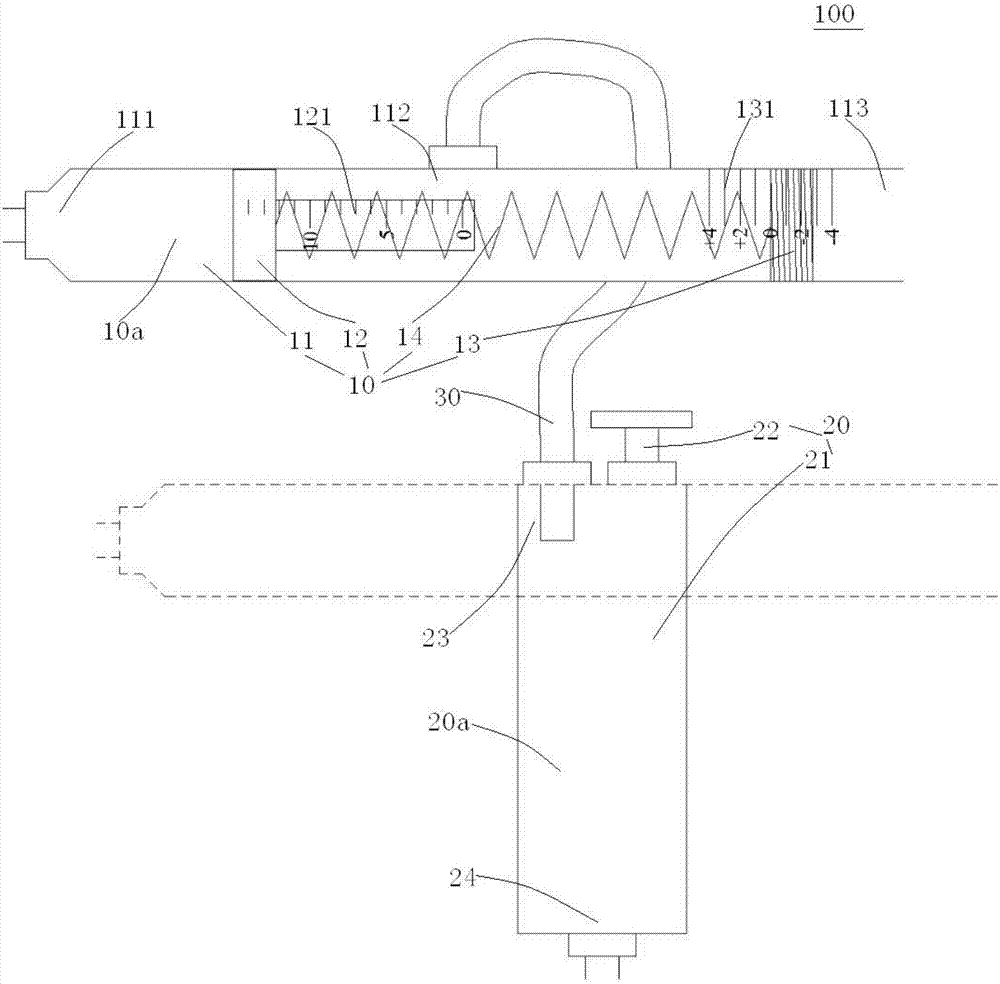
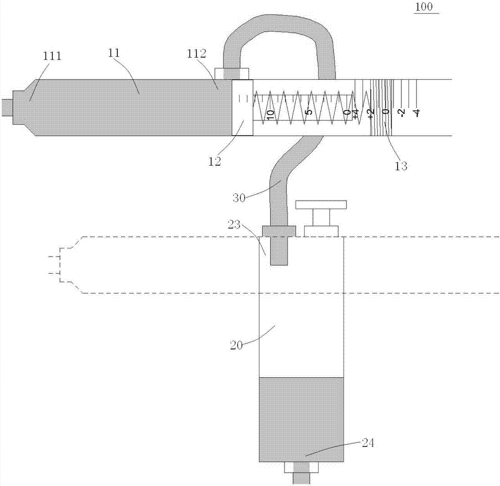
The invention discloses a mechanical cerebrospinal fluid drainage pressure-adjusting device. The mechanical cerebrospinal fluid drainage pressure-adjusting device includes: a pressure infusion tube device, wherein the pressure infusion tube device defines a first accommodation cavity, the first accommodation cavity can hold part of cerebrospinal fluid provisionally, and the pressure infusion tubedevice is used for controlling if the cerebrospinal fluid in the first accommodation cavity flows out or not; a non-pressure infusion tube device, wherein the non-pressure infusion tube device definesa second accommodation cavity and is used for adjusting the pressure of the pressure infusion tube device; a connection device, wherein one end of the connection device is connected to the pressure infusion tube device, and the other end of the connection device is connected to the non-pressure infusion tube device. The cerebrospinal fluid in the first accommodation cavity can flow into the second accommodation cavity through the connection device. The mechanical cerebrospinal fluid drainage pressure-adjusting device may be fixed on a head of a patient, the head position of the patient will not influence on a drainage effect, nursing is very convenient, and the mechanical cerebrospinal fluid drainage pressure-adjusting device is safe and reliable to use.

Description

technical field [0001] The invention relates to the field of medical intracranial pressure regulating equipment, and more specifically, to a mechanical cerebrospinal fluid drainage and pressure regulating device. Background technique [0002] Intracranial hypertension syndrome is caused by a variety of pathogenic factors to increase the intracranial volume, and the intracranial pressure exceeds 1.92kpa, resulting in a series of clinical manifestations such as headache, vomiting, visual impairment and papilledema. [0003] At present, external ventricular drainage is one of the common treatment methods for increased intracranial pressure syndrome. The specific measures are to place the ventricular end of the external ventricular drainage device in the ventricle, and hang the drainage bottle at the external end 10-15cm above the patient's external auditory canal. Under the action of intracranial pressure, the cerebrospinal fluid flows into the drainage bottle, thereby reducing...

Claims


Application Information

Patent Timeline
IPC IPC(8): A61M1/00
CPCA61M2202/0464A61M2205/3331A61M1/74A61M2202/0014
Inventor 李铁键乌优图王劲苏洋
Owner TSINGHUA UNIV
Learn More