
Speed regulating system and speed regulating method for switched reluctance motor

A technology of switched reluctance motor and speed control system, which is applied in control system, motor control, AC motor control, etc. It can solve the problems of speed control system out of step, failure of speed control ability, poor positioning ability, etc., to ensure stability , Guaranteed rigidity, simple effect

Pending Publication Date: 2018-05-04
CHINA INSTITUTE OF ATOMIC ENERGY
View PDF0 Cites 2 Cited by
  • Summary
  • Abstract
  • Description
  • Claims
  • Application Information

AI Technical Summary

Problems solved by technology

[0002] The switched reluctance motor is a synchronous motor. The commutation of the power supply depends on the position of the rotating shaft. Its normal operation requires position sensors (such as incremental encoders, absolute position encoders, resolvers, magnetic Hall effect sensors, etc.) to provide Real-time rotor position information, the controller determines the excited stator phase according to the current position information, so that the stator magnetic field is synchronized with the rotor position; in engineering practice, due to environmental conditions or restrictions, these mechanical devices installed in the switched reluctance motor The position sensor will lead to problems such as low system reliability, high cost, and large volume; if the position sensor is not installed, the speed control system is prone to out-of-step phenomenon, resulting in failure of the speed control ability, and poor positioning ability, unable to accurately step operation

Method used


Image

  • Speed regulating system and speed regulating method for switched reluctance motor
  • Speed regulating system and speed regulating method for switched reluctance motor
  • Speed regulating system and speed regulating method for switched reluctance motor

Examples


Embodiment Construction

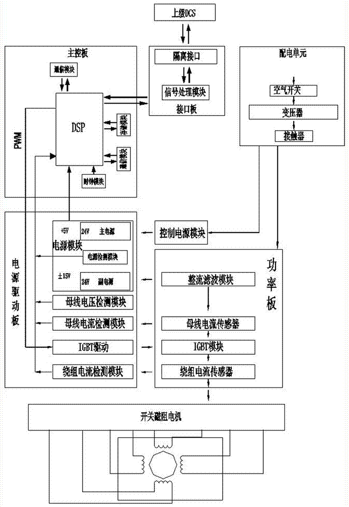
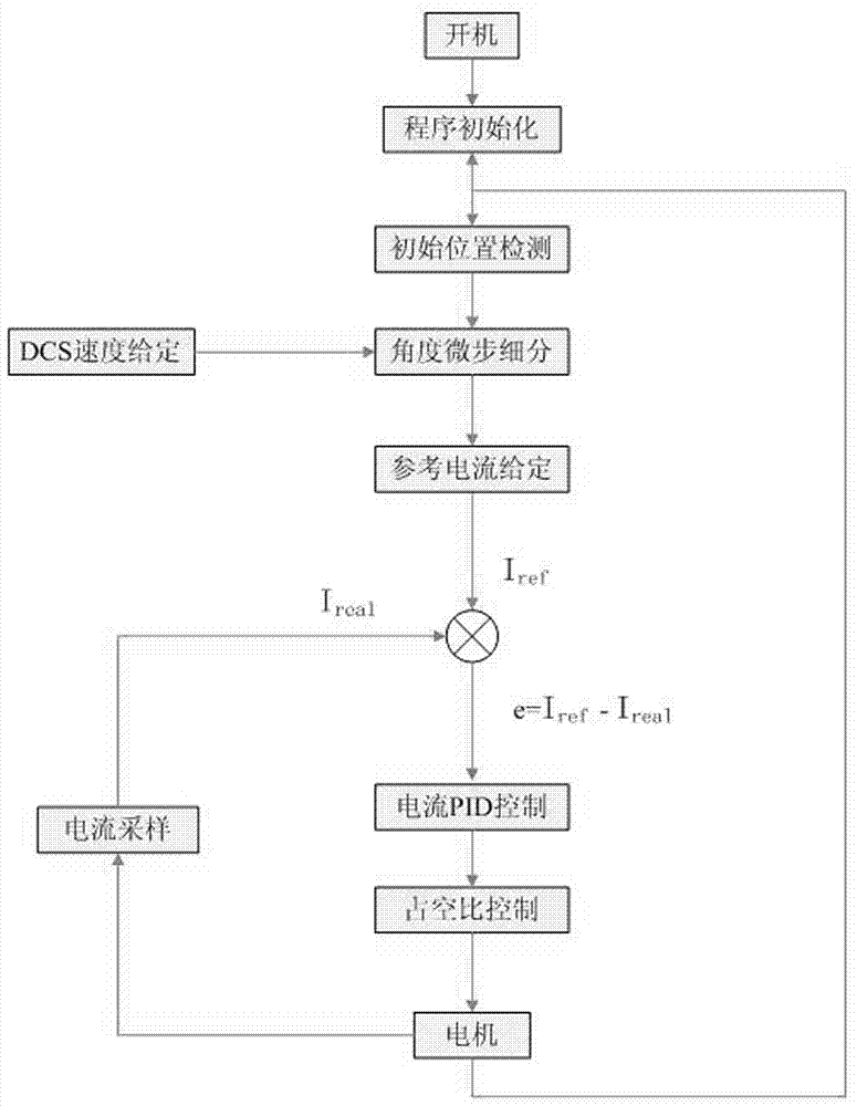
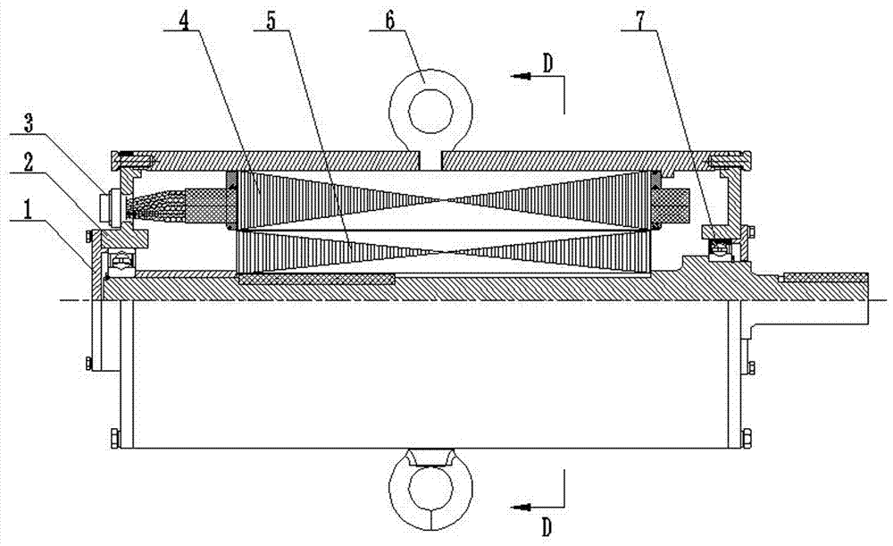
[0035] Such as figure 1 , image 3 , Figure 4 and Figure 5As shown, a switched reluctance motor speed control system includes a superior DCS (distributed control system), a switched reluctance motor and a controller. The switched reluctance motor described in this embodiment is a low-speed DC four-phase synchronous motor. The resistance motor includes bearing outer cover 1, end cover 2, connection terminal 3, stator 4, rotor 5, lifting ring 6 and bearing 7; the stator 4 of the switched reluctance motor includes a frame 11, a stator core 10 and a stator winding 9, and the switch magnetic The rotor 5 of the resistance motor includes a rotor core 8 and a rotating shaft. The rotor core 8 is integrally processed from a whole round steel instead of laminated silicon steel sheets. Although the speed of the motor will be limited, it has good rigidity and is easy to manufacture. And the price is cheap; two light holes 12 are radially processed on the rotor core 8, and the rotor co...


PUM


Abstract

The invention discloses a speed regulating system and speed regulating method for a switched reluctance motor. The speed regulating system includes an upper DCS, the switched reluctance motor and a controller, and the controller comprises a main control board, an interface board, a power distribution unit, a power drive board and a power board. The main control board includes a DCS chip. The powerdrive board includes a power supply unit, an IGBT drive module and a winding current detection module. The power board includes an IGBT module and a winding current sensor. The power distribution unit supplies power to the power board. The winding current detection module is used to collect current information of each phase in a stator winding. The IGBT drive module and the winding current detection module are connected with the IGBT module and the winding current sensor respectively. The signal output end of the winding current detection module is connected with a data collection port of theDCS chip, the signal input end of the IGBT drive module is connected with a PWM signal output end of the DCS chip. The speed regulation of the switched reluctance motor can be achieved without installation of a position sensor, and the speed regulating system and speed regulating method for the switched reluctance motor are high in control accuracy and reliability.

Description

technical field [0001] The invention relates to a speed regulating system and a speed regulating method of a switched reluctance motor, in particular to a speed regulating system and a speed regulating method of a current-controlled switched reluctance motor requiring stepping operation, and belongs to the technical field of motor control. Background technique [0002] The switched reluctance motor is a synchronous motor. The commutation of the power supply depends on the position of the rotating shaft. Its normal operation requires position sensors (such as incremental encoders, absolute position encoders, resolvers, magnetic Hall effect sensors, etc.) to provide Real-time rotor position information, the controller determines the excited stator phase according to the current position information, so that the stator magnetic field is synchronized with the rotor position; in engineering practice, due to environmental conditions or restrictions, these mechanical devices install...

Claims


Application Information

Patent Timeline
IPC IPC(8): H02P25/089H02P25/092H02P6/28H02P6/30H02K11/30H02K11/33H02K1/22
CPCH02K1/22H02K11/30H02K11/33H02P6/28H02P6/30H02P25/089H02P25/092H02P2203/07H02P2203/03H02P2203/11
Inventor 吴宣东胡述静来海丰张道洋张浩王天锋刘平顺周良范红伟刘建波任宁宁苑旭东羊娟
Owner CHINA INSTITUTE OF ATOMIC ENERGY
Learn More