
Wafer edge defect detecting method

An edge defect and wafer technology, applied in the field of wafer edge defect detection, can solve the problems of slow detection speed and low accuracy, and achieve the effect of improving detection speed and accuracy

Inactive Publication Date: 2018-05-04
SHANGHAI HUALI MICROELECTRONICS CORP
View PDF17 Cites 14 Cited by
  • Summary
  • Abstract
  • Description
  • Claims
  • Application Information

AI Technical Summary

Problems solved by technology

[0004] According to the above-mentioned problems existing in the prior art, a method for detecting wafer edge defects is now provided, aiming to solve the problems of slow detection speed and low accuracy in the prior art by manually using a microscope to detect wafers

Method used


Image

  • Wafer edge defect detecting method
  • Wafer edge defect detecting method
  • Wafer edge defect detecting method

Examples


Embodiment Construction

[0026] The present invention will be further described below in conjunction with the accompanying drawings and specific embodiments, but not as a limitation of the present invention.

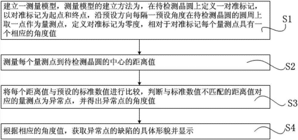
[0027] In a preferred embodiment of the present invention, as Figure 1-3 As shown, a method for detecting wafer edge defects is provided, comprising the following steps:

[0028] Step S1. Establish a measurement model. The method of establishing the measurement model is to define an alignment mark on the wafer to be inspected, with the alignment mark as the starting point and the end point, and place the alignment mark on the wafer to be inspected at every preset angle along the preset direction. Take a point on the circumference of the circle as the measurement point, define the alignment mark as zero degrees, and each measurement point has a corresponding angle value relative to the alignment mark;

[0029] Step S2, measuring the distance value from each measurement point to the center of the...


PUM


Abstract

The invention belongs to the technical field of semiconductor manufacturing and discloses a wafer edge defect detecting method. The method includes steps: establishing a measurement model which comprises a plurality of measurement points corresponding to the edge of a to-be-detected wafer, wherein each measurement point has a corresponding angle value; measuring a value of distance between each measurement point and the center of the to-be-detected wafer; comparing each distance value with a preset standard numerical value, judging that the measurement points corresponding to the values of distance smaller than the standard numerical value are abnormal points, and acquiring the angle values of the abnormal points; according to the corresponding angle values, acquiring specific defect morphologies of the abnormal points to display. The method has advantages that by defining a plurality of measurement points, in one-to-one correspondence to the angle values, at the edge of the wafer, thevalue of distance between each measurement point and the center of the wafer is measured and compared with the standard numerical value to obtain defect positions, then the defect positions are detected to obtain specific morphologies of the defects, and accordingly detection speed and accuracy rate are increased.

Description

technical field [0001] The invention relates to the technical field of integrated circuit manufacturing, in particular to a method for detecting wafer edge defects. Background technique [0002] An integrated circuit (integrated circuit) is a tiny electronic device or component. After oxidation, photolithography, diffusion, epitaxy, aluminum evaporation and other semiconductor manufacturing processes, the semiconductors, resistors, capacitors and other components required to form a circuit with certain functions and the connecting wires between them are all integrated on a small silicon chip. , and then solder the electronics packaged in a package. During the manufacture of integrated circuits, there is a possibility of defects forming on the wafer during each process flow. With the development of semiconductor technology, semiconductor devices tend to be miniaturized more and more, and the influence of defects on the wafer is increasing in the semiconductor process. There...

Claims


Application Information

Patent Timeline
IPC IPC(8): H01L21/66
CPCH01L22/20H01L22/24
Inventor 冯亚丽顾晓芳倪棋梁龙吟陈宏璘
Owner SHANGHAI HUALI MICROELECTRONICS CORP
Learn More