
Rut testing instrument and testing method thereof

A rut and sensor technology, which is applied in the field of detection instruments for automatic detection of road ruts, can solve the problems of reducing maintenance costs, low detection efficiency, and inadaptability to the road traffic operating environment, and achieves the effect of improving detection speed and accuracy

Active Publication Date: 2008-11-12
HARBIN INST OF TECH
View PDF0 Cites 13 Cited by
  • Summary
  • Abstract
  • Description
  • Claims
  • Application Information

AI Technical Summary

Problems solved by technology

Most of the current rutting detection in our country adopts manual methods, using a ruler as a detection tool, and using manual direct measurement, which is outdated and extremely incompatible with the operating environment of modern road traffic
At t

Method used


Image

  • Rut testing instrument and testing method thereof
  • Rut testing instrument and testing method thereof

Examples


Example Embodiment

[0016] Example 1:

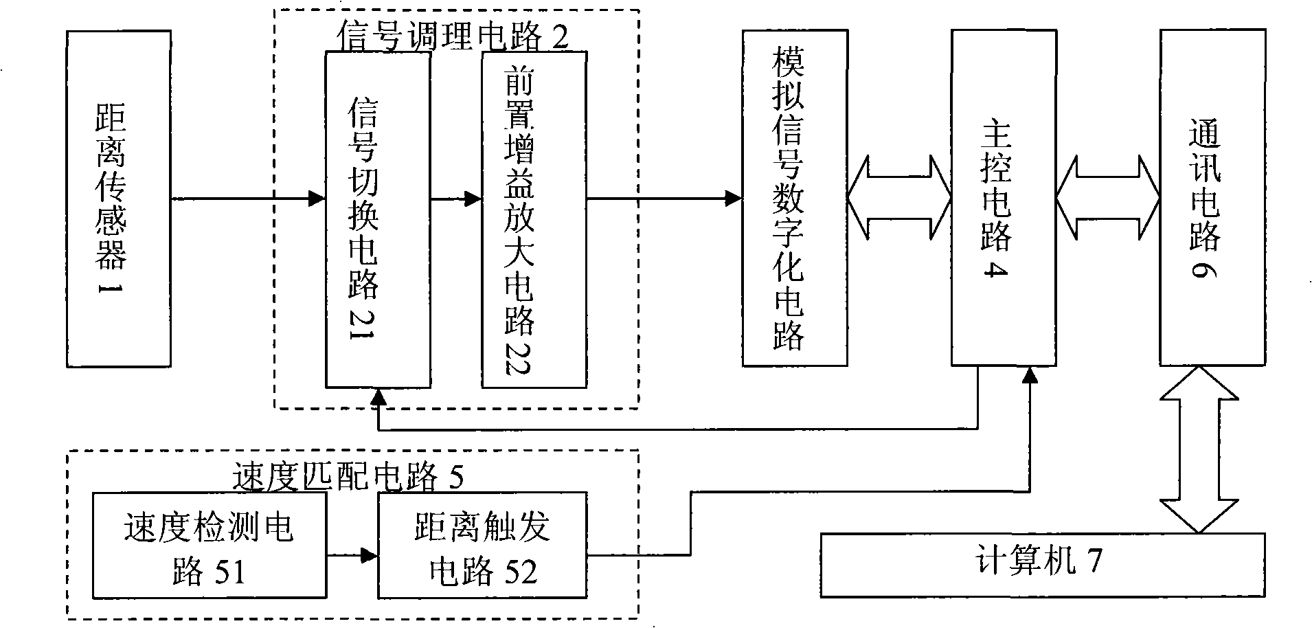
[0017] Combine figure 1 The road rut detection instrument of this embodiment includes: a distance sensor part 1, a signal conditioning circuit part 2, an analog signal digitizing circuit part 3, a main control circuit part 4, a speed matching circuit part 5, a communication circuit part 6 and a computer part 7. This instrument is installed on the car.

[0018] The distance sensor part 1 is composed of a plurality of sensors for measuring distances. In this embodiment, 17 infrared distance measuring sensors are used, and the sensors are arranged in a straight line with an interval of 20 cm, and are perpendicular to the driving direction of the car.

[0019] The signal conditioning circuit 2 is composed of a signal switching circuit 21 and a pre-gain amplifier circuit 22; the signal switching circuit 21 is composed of a cd74hc4051 analog switch chip, and the pre-gain amplifier circuit 22 is composed of an ad620 instrument operational amplifier chip.

[0020] Ana...

Example Embodiment

[0038] Example 2:

[0039] Combine figure 1 The road rutting detection instrument of this embodiment includes: a distance sensor part 1, a signal conditioning circuit part 2, an analog signal digitizing circuit part 3, a main control circuit part 4, a speed matching circuit part 5, a communication circuit part 6 and a computer part 7. This instrument is installed on the car.

[0040] The distance sensor part 1 is composed of a plurality of sensors for measuring distances. In this embodiment, 33 laser distance measuring sensors are used, each of which is 10 cm apart, arranged in a straight line, perpendicular to the driving direction of the car.

[0041] The signal conditioning circuit 2 is composed of a signal switching circuit 21 and a pre-gain amplifier circuit 22; the signal switching circuit 21 is composed of a cd74hc4051 analog switch chip, and the pre-gain amplifier circuit 22 is composed of an ad620 instrument operational amplifier chip.

[0042] Analog signal digitization...


PUM


Abstract

The invention provides a rut detecting device and a detecting method thereof, and the rut detecting device comprises a distance sensor part, a signal conditioning circuit part, an analog signal digitizing circuit part, a main control circuit part, a speed matching circuit part, a communication circuit part and a computer part; the distance sensor part consists of at least one sensor used for measuring distance; the signal conditioning circuit part consists of a signal switching circuit and a pre-amplifier gain circuit; the analog signal digitizing circuit part consists of an analog-to-digital converter; the main control circuit part consists of a microprocessor circuit part; the communication circuit part consists of communication devices; the speed matching circuit part consists of a speed detecting circuit and a distance triggering circuit; the computer part consists of a computer containing a processor and a storage and having the functions of displaying, calculating and storing. The rut detecting device improves the speed and the precision of rut detecting.

Description

(1) Technical field [0001] The invention relates to a rut detection technology, in particular to a detection instrument for automatically detecting road ruts and a detection method thereof. (2) Technical background [0002] With the rapid development of my country's transportation, accurate and timely detection of road damage has become an increasingly prominent problem. As one of the main disease forms of asphalt pavement in our country, rutting seriously affects driving safety and transportation economy. Rutting detection and evaluation is one of the important basis for determining the maintenance plan, and it is also an indispensable technical content for long-term monitoring of the road surface. Most of the current rutting detection in our country adopts manual methods, using a ruler as a detection tool, and using manual direct measurement. The means are backward and extremely unsuitable for the operating environment of modern road traffic. At the same time, due to the...

Claims


Application Information

Patent Timeline
IPC IPC(8): E01C23/01G01S17/08
Inventor 王华侯相琛马松林
Owner HARBIN INST OF TECH
Learn More