
Support for double-camera assembly, split support type double-camera assembly and assembling method

An assembly method and a bracket-type technology, which are applied to the machine table/bracket, supporting machine, camera body, etc., can solve the problems of high scrapping cost, inability to further adjust the accuracy, affecting positioning accuracy, etc., and reduce maintenance or scrapping costs. Effect

Pending Publication Date: 2018-05-04
SHANGHAI MORUAN COMM TECH
View PDF13 Cites 2 Cited by
  • Summary
  • Abstract
  • Description
  • Claims
  • Application Information

AI Technical Summary

Problems solved by technology

[0003] The technical problem to be solved by the present invention is to overcome the defects in the prior art that the double-camera using a common substrate is easily deformed and affects the positioning accuracy, and the accuracy cannot be further adjusted once the production is completed, and the scrap cost is high. Bracket for dual-camera, split-bracket-type dual-camera and assembly method for relative accuracy of optical axes

Method used


Image

  • Support for double-camera assembly, split support type double-camera assembly and assembling method
  • Support for double-camera assembly, split support type double-camera assembly and assembling method
  • Support for double-camera assembly, split support type double-camera assembly and assembling method

Examples


Embodiment 1

[0031] Such as figure 1 As shown, this embodiment provides a bracket for dual-camera, including a bracket body 1, and the bracket body 1 is provided with a first positioning hole 101, a second positioning hole 102, and four housing positioning locking points 103 and four PCB board positioning locking points 104; the bracket body 1 is made of magnesium-aluminum alloy material.

[0032] The first positioning hole 101 is used to fix the first lens module, and a first gap for calibration is reserved between the first positioning hole 101 and the first lens module;

[0033] The second positioning hole 102 is used to fix the second lens module, and a second gap for calibration is reserved between the second positioning hole 102 and the second lens module;

[0034] The housing positioning and locking points 103 are used to fix the bracket body 1 on the housing, wherein two of the housing positioning locking points 103 are arranged at one end of the bracket body 1, and the other two ...

Embodiment 2

[0040] Such as figure 2 As shown, this embodiment provides a split bracket type dual camera, including a first lens module 2, a second lens module 3 and the bracket 4 described in Embodiment 1, the first lens module 2 is fixed Connected to the first positioning hole, the second lens module 3 is fixed to the second positioning hole.

[0041] The split-bracket dual-camera provided in this embodiment can meet the requirements of different Sensor SMT processes. Whether the Sensor adopts CSP (Chip Scale Package, chip scale package), COB (Chips on Board, chip on board package), PLCC (Plastic Leaded Chip Carrier, special pin chip package) and other packages, all can meet the relevant parameters. In addition, it can also meet the design requirements of different Lens. Regardless of the difference between Lens and Holder design, almost all of them can achieve the design process precision, without having to open the Holder mold separately.

[0042]In this embodiment, during use of t...

Embodiment 3

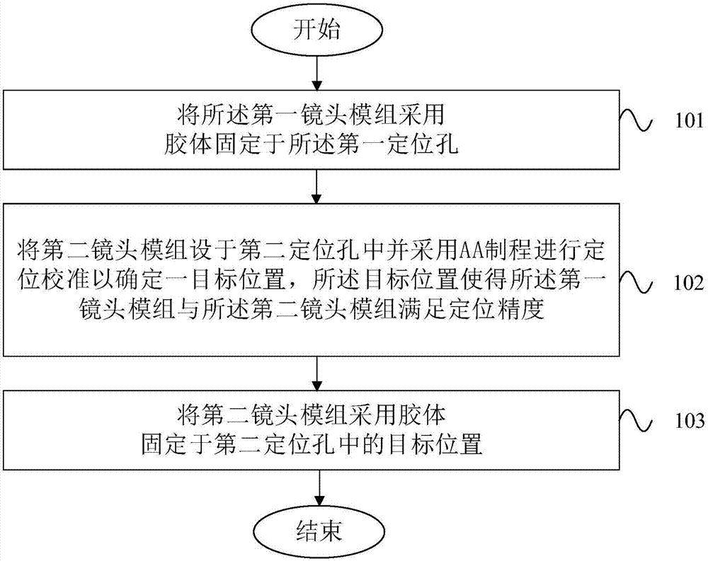
[0044] Such as image 3 As shown, this embodiment provides a method for assembling the split bracket type dual camera for assembling the split bracket type dual camera described in Example 2. The assembly method includes the following steps:

[0045] Step 101, fixing the first lens module to the first positioning hole with colloid;

[0046] Step 102: Set the second lens module in the second positioning hole and perform positioning calibration using the AA process to determine a target position, the target position makes the first lens module and the second The lens module meets the requirements of positioning accuracy;

[0047] Step 103 , fixing the second lens module at the target position in the second positioning hole with colloid.

[0048] In this embodiment, in order to achieve the required accuracy, the AA process is used for calibration during the assembly process. The assembly method is to fix the first lens module in advance, and adjust the second lens module throug...


PUM


Abstract

The invention discloses a support for a double-camera assembly, the split support type double-camera assembly and an assembling method. The support comprises a support body, and the support body is provided with a first positioning hole, a second positioning hole, a plurality of shell positioning locking points and a plurality of PCB positioning locking points. The first positioning hole is used for being fixedly connected with a first camera module, and a first gap for calibration is reserved between the first positioning hole and the first camera module. The second positioning hole is used for being fixedly connected with a second camera module, and a second gap for calibration is reserved between the second positioning hole and the second camera module. The shell positioning locking points are used for fixedly connecting the support body to a shell. The PCB positioning locking points are used for fixedly connecting a PCB to the support body. The gaps for calibration are reserved between the camera modules and the positioning holes, the relative precision of optical axes of two cameras can be adjusted conveniently, and the separate design of the PCB, the camera modules and the support is beneficial for reduction of the repair or scrap cost.

Description

technical field [0001] The invention belongs to the field of dual cameras, and in particular relates to a bracket for a dual camera, a split bracket type dual camera and an assembly method. Background technique [0002] Dual cameras are widely used in VR (virtual reality), AR (augmented reality), drones, robots, smart cars and other fields for depth calculation, scene reconstruction, feature point tracking, etc. The existing general long-distance dual-camera adopts a common substrate technical solution, such as the dual-camera of Sony PSVR (a virtual reality head-mounted display), which has the following disadvantages: First, when the distance between the dual-camera (Printed circuit board) has limited strength, and is easily affected by temperature and humidity, and is easy to deform, which will affect the parameters of the dual camera and affect the positioning accuracy. Second, since the common substrate adopts a single SMT (Surface Mount Technology), if there is a high ...

Claims


Application Information

Patent Timeline
Patent Type & Authority Applications(China)
IPC IPC(8): F16M11/04G03B17/56G03B30/00
CPCG03B17/561F16M11/04
Inventor 张元通韦正华孙学逊刘羽鹏
Owner SHANGHAI MORUAN COMM TECH
Learn More