
Vehicle seat

A technology for seats and vehicles, which is applied to vehicle seats, seat frames, vehicle components, etc., can solve problems such as inability to connect through holes 30, and achieve the effects of improving appearance design and suppressing tension relaxation

Active Publication Date: 2018-05-04
TACHI S CO LTD
View PDF21 Cites 0 Cited by
  • Summary
  • Abstract
  • Description
  • Claims
  • Application Information

AI Technical Summary

Problems solved by technology

[0003] However, in the prior art described above, since the opening of the through hole 30 on the rear side of the seat back SB is covered with the skin material 6 (skin), the through hole 30 cannot communicate with the front side and the rear side of the seat back SB.

Method used


Image

  • Vehicle seat
  • Vehicle seat
  • Vehicle seat

Examples


Embodiment Construction

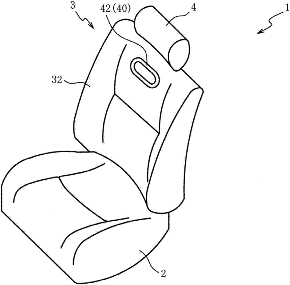
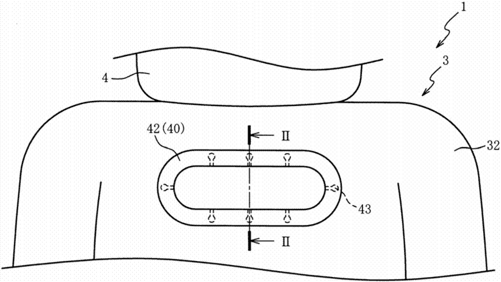
[0033] Hereinafter, preferred embodiments of the present invention will be described with reference to the drawings. First, the overall structure of the vehicle seat 1 will be described with reference to FIG. 1 . Figure 1A is a perspective view of the vehicle seat 1 according to the first embodiment of the present invention, Figure 1B It is a front view of the vehicle seat 1 . also, Figure 1B A part of the vehicle seat 1 is omitted from illustration.

[0034] As shown in FIG. 1 , a vehicle seat 1 is a seat mounted on a vehicle (for example, an automobile or a railway vehicle). The vehicle seat 1 includes a seat cushion 2 forming a seat surface, a seat back 3 connected to a rear end of the seat cushion 2 to form a backrest, and a headrest 4 arranged at an upper end of the seat back 3 .

[0035] A through hole 34 is formed on the upper end side of the seat back 3 (see figure 2 ), insert the first cover member 40 and the second cover member 50 in the through hole 34 (the ...


PUM


Abstract

The invention provides a vehicle seat that can improve appearance. The vehicle seat includes a first cover member (40) to which a terminal of a first skin (32) is stitched and a second cover member (50) to which a terminal of a second skin (33) is stitched. The first cover member (40) and the second cover member (40) are joined together. This ensures reducing a displacement of the first skin (32)and the second skin (33) relative to the first cover member (40) and the second cover member (50). This ensures reducing the first skin (32) and the second skin (33) being turned up at an outer edge of a flange portion (42) of the first cover member (40) and an end portion of the second cover member (50) on the second skin (33) side. This ensures improving appearance of the vehicle seat (1).

Description

technical field [0001] The present invention relates to a vehicle seat, and particularly relates to a vehicle seat capable of improving designability. Background technique [0002] A technique is known in which a through hole is formed in a cushioning member disposed on a seat back of a vehicle seat, and the inner peripheral surface of the through hole is covered with a cover member made of a resin material. For example, Patent Document 1 discloses a vehicle seat that includes a functional part 1 (cover member) having a cylindrical body 10 and a flange 11, and inserts a functional part 1 into a through hole 30 formed in a pad 3 (cushion member). Part 1. [0003] However, in the prior art described above, since the opening of the through hole 30 on the rear side of the seat back SB is covered with the skin material 6 (skin), the through hole 30 cannot communicate with the front side and the rear side of the seat back SB. . [0004] prior art literature [0005] patent doc...

Claims


Application Information

Patent Timeline
Patent Type & Authority Applications(China)
IPC IPC(8): B60N2/58B61D33/00
CPCB60N2/5825B60N2/5833B60N2/5866B60N2/5875B60N2/5883B61D33/0035B60N2/64B60N2/68B60N2/5816
Inventor 田口雅之
Owner TACHI S CO LTD
Learn More