Permanent magnetism eddy current shaft coupling

A permanent magnet eddy current and shaft coupling technology, which is applied in the direction of electrical components, electromechanical devices, electromechanical transmission devices, etc., can solve the problem of less heat generation, and achieve the effects of less heat generation, low cleaning frequency and stable torque transmission

Inactive Publication Date: 2018-05-01
BEIJING SINO POWER RUNZE ENVIRONMENTAL PROTECTIONCO
View PDF12 Cites 0 Cited by
  • Summary
  • Abstract
  • Description
  • Claims
  • Application Information

AI Technical Summary

Problems solved by technology

[0004] In view of the above problems, the purpose of the present invention is to provide a permanent magnet eddy current coupling. Compared with the existing patented technology, the stability of torque transmission is greatly increased, and the air convection is formed by itself without increasing the mechanism. Effectively solve the problem of heat generation, and can be applied to poor power grid quality, high humidity, dusty, flammable and explosive environments, and even meet the requirements of use in the case of "shocking electricity", with green energy saving, no-load start, short start-up time, Less heat, wide speed range and many other advantages

Method used


Image

  • Permanent magnetism eddy current shaft coupling
  • Permanent magnetism eddy current shaft coupling
  • Permanent magnetism eddy current shaft coupling

Examples


Embodiment Construction

[0031] Embodiments according to the present invention will be described in detail below with reference to the accompanying drawings.

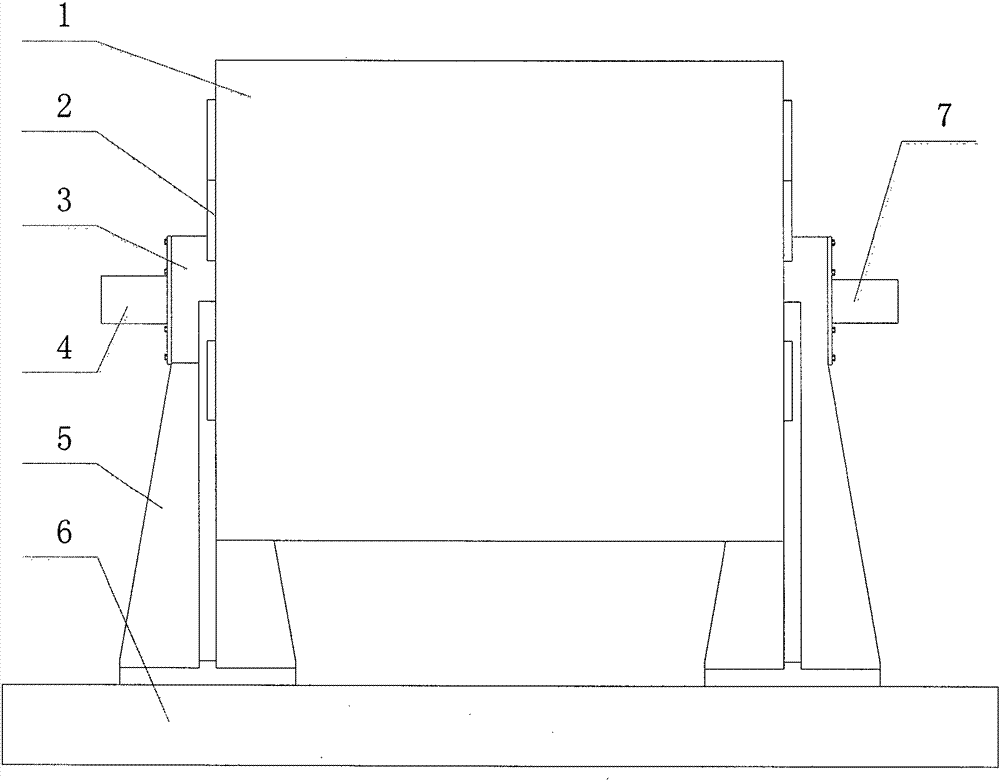
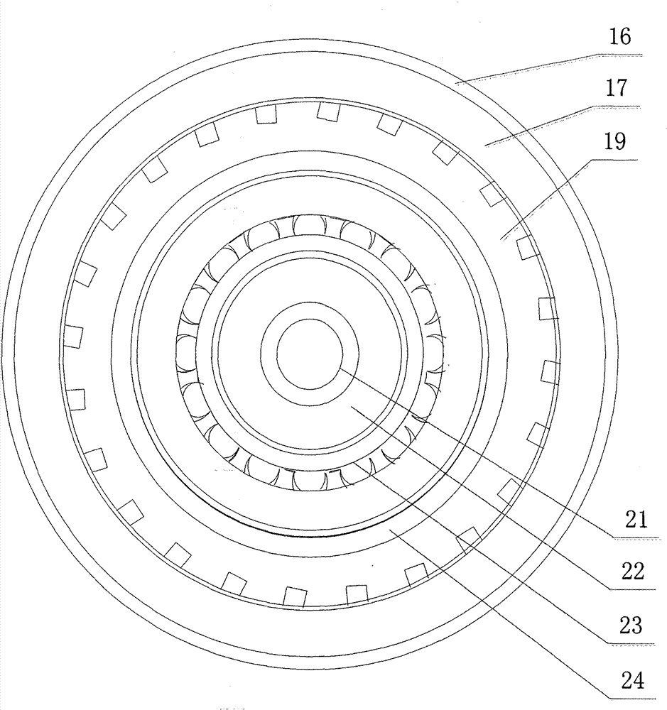
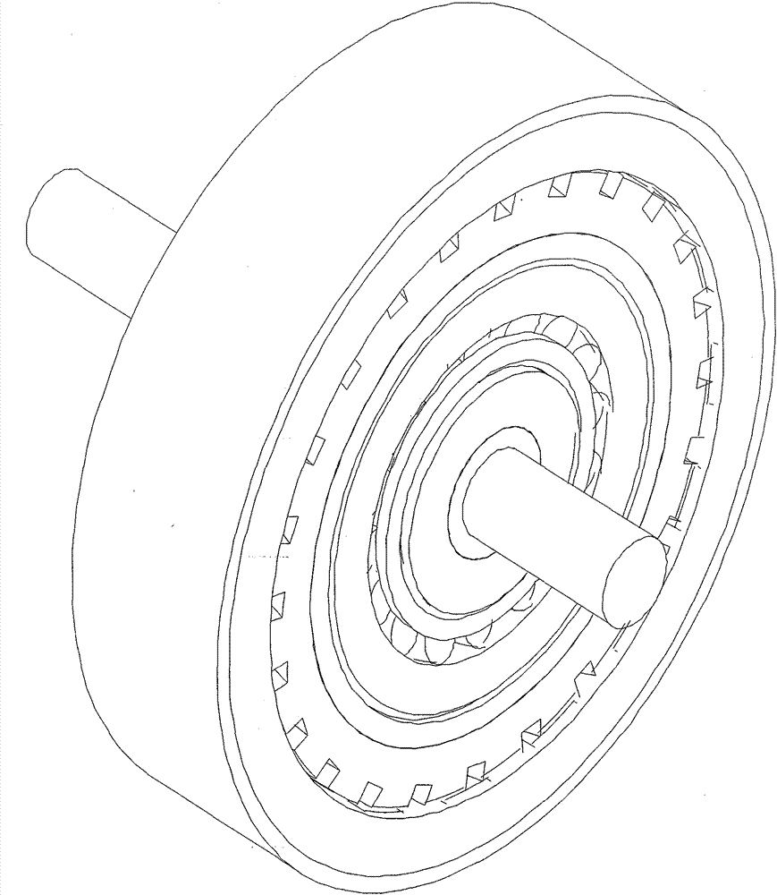
[0032] As shown in the drawings, the permanent magnet eddy current coupling includes: including: active mechanism, driven mechanism, moving mechanism and supporting mechanism, etc.; active mechanism, including active rotor 17, permanent magnet 18, shielding bushing 16, etc. The permanent magnet 18 is wedge-shaped embedded in the active rotor 17, so that the permanent magnet 18 cooperates more firmly with the active rotor 17 during the rotation of the active rotor 17, effectively reducing the vibration and noise caused by the installation gap; the shielding sleeve 16 is located on the outside of the active rotor 17 and moves together with the active rotor 17. The active rotor 17 is made of non-magnetic material, and the shielding lining 16 is made of magnetic material to optimize the thickness of the active rotor, that is, to maximize the magneti...


PUM


Abstract

The invention provides a permanent magnetism eddy current shaft coupling, which can realize highly-efficient torque transmission (the efficiency can be as high as 98%) and stable torque transmission (the fluctuation will not exceed 0.5%). The permanent magnetism eddy current shaft coupling comprises permanent magnets, whose number or set number is the multiple of 4, and which conduct auxiliary magnetizing, and are inlaid in an active rotor in a wedge-shaped manner. The vibration and noise generated by installation gap can be effectively reduced. The permanent magnetism eddy current shaft coupling also comprises a driven rotor, which is provided with a helical groove. Accordingly, the output torque is high in stability, and vibration and noise when the system works can be greatly reduced; cross ventilation can be formed, and a large amount of heat can be taken away, and the heating problem can be resolved. The permanent magnetism eddy current shaft coupling also comprises an axial moving mechanism, which adopts the cooperation mode of an electric performer and sliding shoes. Two ends of the electric performer adopt ball joint. The permanent magnetism eddy current shaft coupling alsocomprises an air filter, which can reduce pollution of air-suspending particles like ferromagnetism particles and coal powder to the system. The invention is advantageous in that maintenance cost islow (no vulnerable parts are provided and cleaning frequency is low); environment can be protected and energy can be saved; flexible starting is provided, and heating is little; speed-regulating scopecan be wide; energy conservation and emission reduction can be realized.

Description

technical field [0001] The invention relates to a permanent magnet eddy current coupling. Background technique [0002] my country is rich in resources and is a country with a large production capacity, but it is also a country with a large energy consumption. The phenomenon of energy and resource waste is serious, and the utilization rate is low. Saving energy and reducing consumption has become a hot spot of social concern and an important issue that must be considered in the design process. Equipment such as pump motors and fans are widely used in social production, and their energy consumption accounts for a large proportion of total social energy consumption, accounting for about 31.3%. Due to the design deficiencies of pump motors and fans currently used in our country, especially in large-scale drive equipment, they are still relatively backward compared with foreign developed countries, and in the process of matching motors and loads, there are often "big horses and ...

Claims


Application Information

Patent Timeline
Patent Type & Authority Applications(China)
IPC IPC(8): H02K51/00
Inventor 刘丹
Owner BEIJING SINO POWER RUNZE ENVIRONMENTAL PROTECTIONCO
Why Eureka
Try Eureka