


Quick Research
Generate reliable direction feasibility study reports for your R&D in just a few steps.

Technical Q&A
Discover and master advanced knowledge NOW. Basics, ideas, possibilities, all at once.

Find Solutions
As an expert in R&D theories, this can generate solutions to your technical problems instantly.

Evaluate Feasibility
Analyze your overall solution with one click, know your potential R&D risks in advance.

Monitor Landscape
Get weekly tech updates, stay abreast of the latest tech innovations and key insights.
Fixing mechanism
A fixing mechanism and first-line technology, applied in the direction of electrical components, etc., can solve problems such as different cable diameters and poor applicability of cable fixing fixtures, and achieve good applicability, excellent shaping effect, and good fixing effect Effect
- Summary
- Abstract
- Description
- Claims
- Application Information
AI Technical Summary
Problems solved by technology
Method used
Image

Examples
Embodiment 1
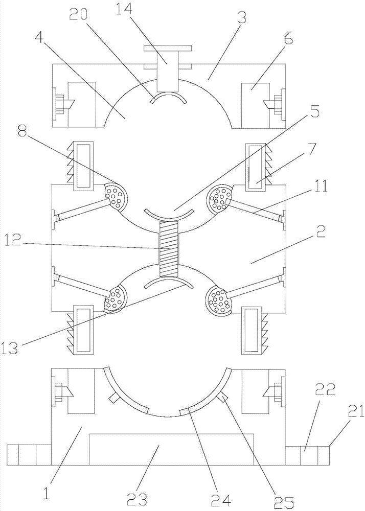
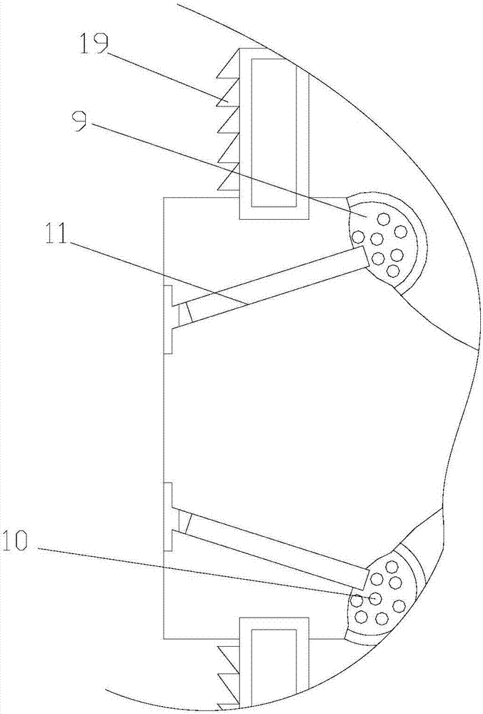
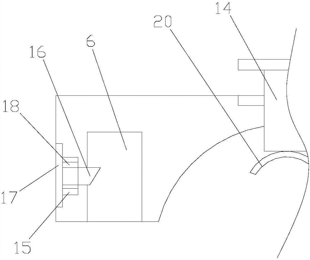
[0042] Such as Figure 1-3 As shown, a fixing mechanism includes a lower clamp 1, a middle clamp 2 and an upper clamp 3, the lower clamp 1 and the upper clamp 2 are provided with first wire slots 4, the upper end surface of the middle clamp 2 and the lower The end faces are provided with the second wire slot 5 matched with the first wire slot 4, the lower clamp 1 and the upper clamp 3 are provided with jacks 6, and the upper end surface and the lower end surface of the middle clamp 2 are provided with The insertion rod 7 matched with the socket 6, the insertion rod 7 fits with the socket 6, an arc-shaped depression (not shown) is opened on the groove wall of the second wire groove 5, and the groove of the second wire groove 5 The wall is provided with a silica gel sheet 8 for covering the depression, and the silica gel sheet 8 is bonded to the groove wall of the second wire groove 5, and a storage chamber 9 is formed between the silica gel sheet 8 and the arc-shaped depression...
Embodiment 2
[0050] Such as Figure 1-3 As shown, a fixing mechanism includes a lower clamp 1, a middle clamp 2 and an upper clamp 3, the lower clamp 1 and the upper clamp 2 are provided with first wire slots 4, the upper end surface of the middle clamp 2 and the lower The end faces are provided with the second wire slot 5 matched with the first wire slot 4, the lower clamp 1 and the upper clamp 3 are provided with jacks 6, and the upper end surface and the lower end surface of the middle clamp 2 are provided with The insertion rod 7 matched with the socket 6, the insertion rod 7 fits with the socket 6, an arc-shaped depression (not shown) is opened on the groove wall of the second wire groove 5, and the groove of the second wire groove 5 The wall is provided with a silica gel sheet 8 for covering the depression, and the silica gel sheet 8 is bonded to the groove wall of the second wire groove 5, and a storage chamber 9 is formed between the silica gel sheet 8 and the arc-shaped depression...
PUM
| Property | Measurement | Unit |
|---|---|---|
| melting point | aaaaa | aaaaa |
| melting point | aaaaa | aaaaa |
| melting point | aaaaa | aaaaa |
Abstract
Description
Claims
Application Information
 - R&D Engineer
- R&D Manager
- IP Professional
- Industry Leading Data Capabilities
- Powerful AI technology
- Patent DNA Extraction
Browse by: Latest US Patents, China's latest patents, Technical Efficacy Thesaurus, Application Domain, Technology Topic, Popular Technical Reports.
© 2024 PatSnap. All rights reserved.Legal|Privacy policy|Modern Slavery Act Transparency Statement|Sitemap|About US| Contact US: help@patsnap.com