A self-locking crimping terminal button connection method

A connection method and self-locking technology, which is applied in the direction of connection, conductive connection, clamping/spring connection, etc., can solve problems such as burn-in, crimping handle lack of fixation, poor contact, etc., to improve sensitivity and smoothness, Improved convenience and reliability, reduced rotational resistance

Active Publication Date: 2019-07-12
STATE GRID CHONGQING ELECTRIC POWER CO ELECTRIC POWER RES INST +1
View PDF5 Cites 0 Cited by
  • Summary
  • Abstract
  • Description
  • Claims
  • Application Information

AI Technical Summary

Problems solved by technology

[0002] There are the following problems in the installation process of the electric energy meter for metering: it is necessary to repeatedly operate the screw of the terminal button, which is time-consuming and laborious, and the work efficiency is low; In this way, if the crimping is too tight, the wire will be damaged. If the crimping is not enough, it may cause poor contact or open circuit, and the operation risk is high; temperature rise, causing burning
[0003] There is an existing structural scheme for shrapnel crimping to realize electrical connection and mechanical fixation, but this scheme has the following problems: the crimping handle lacks fixation after being pressed in place, and the crimping effect will be unsatisfactory due to the elastic rebound of the shrapnel; The internal space of the box is limited, the handle structure only considers the crimping function of the shrapnel, and there are defects in the release structure design for removing the wiring.

Method used


Image

  • A self-locking crimping terminal button connection method
  • A self-locking crimping terminal button connection method
  • A self-locking crimping terminal button connection method

Examples


Embodiment 1

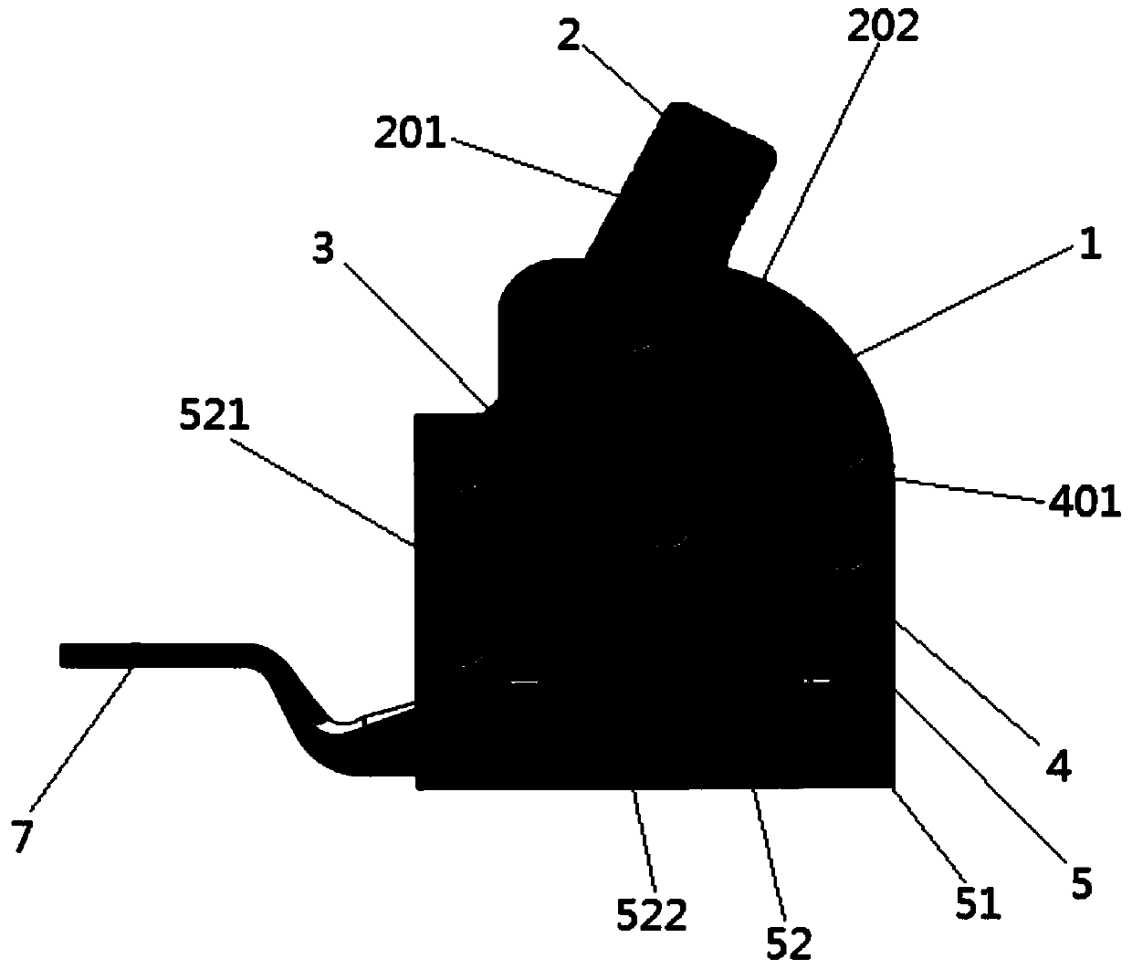
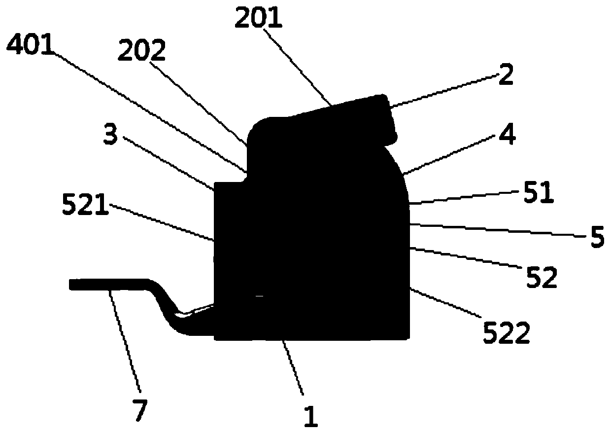
[0044] Embodiment 1: The shrapnel 5 is made of iron shrapnel; it enters the crimping state from the natural state, and the wire is inserted into the end button box from the round hole 6 at the bottom end, and after being tightly connected with the iron shrapnel, the operator depresses the crimping handle 2 . The crimping handle pawl 202 fixed by welding on the lower end of the crimping handle rod 201 drives the transmission ratchet 4 to rotate clockwise, thereby driving the elastic piece 5 to press down, and at the same time completes the connection and tightening of the wire. When entering the crimping state, the included angle between the first crimping piece 521 and the second crimping piece 522 is 10 degrees.

[0045]From the crimping state to the natural state, the crimping handle 2 is directly operated or the crimping handle 2 is operated by an external tool, and the crimping handle 2 is deflected upward. During the upward deflection of the crimping handle 2 , the crimpi...

Embodiment 2

[0047] Embodiment 2: The shrapnel 5 is made of copper shrapnel; from the crimping state into the natural state, directly operate the crimping handle 2 or operate the crimping handle 2 through an external tool to deflect the crimping handle 2 upward. During the upward deflection of the crimping handle 2 , the crimping handle pawl 202 fixed at the lower end of the crimping handle rod 201 drives the transmission ratchet 4 to rotate counterclockwise. At this time, the elastic piece 5 cancels the pressure on the access wire, so that the wire that has not been crimped is taken out from the round hole 6 at the lower end of the terminal box. When entering the natural state, the included angle between the first crimping piece 521 and the second crimping piece 522 is 30 degrees.

[0048] Entering the crimping state from the natural state, the wire is inserted into the terminal button box from the round hole 6 at the bottom end, and after being tightly connected with the iron shrapnel, t...

Embodiment 3

[0050] Embodiment 3: The shrapnel 5 is made of aluminum shrapnel; it enters the crimping state from the natural state, and the wire is inserted into the end button box from the round hole 6 at the bottom end, and after being tightly connected with the iron shrapnel, the operator presses down the crimping handle 2. The crimping handle pawl 202 fixed by welding on the lower end of the crimping handle rod 201 drives the transmission ratchet 4 to rotate clockwise, thereby driving the elastic piece 5 to press down, and at the same time completes the connection and tightening of the wire. When entering the crimping state, the included angle between the first crimping piece 521 and the second crimping piece 522 is 10 degrees.

[0051] From the crimping state to the natural state, the crimping handle 2 is directly operated or the crimping handle 2 is operated by an external tool, and the crimping handle 2 is deflected upward. During the upward deflection of the crimping handle 2 , the...


PUM


Abstract

The invention discloses a self-locking method for connecting crimping end buttons, which comprises the steps of setting a crimping handle rod in an end button box, one end of the crimping handle rod is provided with a crimping handle pawl, and the other end of the crimping handle rod is It is located outside the terminal button box; a transmission ratchet is set under the crimping handle, and the transmission ratchet is set in the crimping type terminal box. There is a shrapnel, and the shrapnel is attached to the bottom of the crimping type terminal box; the spring is arranged in the crimping type terminal box, and the spring is connected with the ratchet of the crimping handle; a through hole is opened on the crimping type terminal box. The beneficial effects obtained by the invention are: the sensitivity and smoothness of the operation of the crimping handle can be improved; the stability of the electrical connection can be improved; the smoothness of crimping and removal can be improved; the convenience and reliability of the circuit operation of the electric energy meter can be improved.

Description

technical field [0001] The invention relates to the technical field of electric energy meter installation, in particular to a self-locking crimping terminal button connection method. Background technique [0002] The following problems exist in the installation process of the metering electric energy meter: it is necessary to repeatedly operate the terminal button screws, which is time-consuming and laborious, and the work efficiency is low; In order to squeeze through the screw, if the crimping is too tight in this way, the wire will be damaged. Insufficient crimping may cause poor contact or open circuit, and the operation risk is high; The temperature rises, causing the watch to burn. [0003] There are existing structural solutions to achieve electrical connection and mechanical fixation by crimping shrapnel, but this solution has the following problems: the crimping handle lacks fixation after being pressed in place, and the crimping effect is not ideal due to the elas...

Claims


Application Information

Patent Timeline
Patent Type & Authority Patents(China)
IPC IPC(8): H01R4/52H01R9/00
CPCH01R4/52H01R9/00H01R4/48365
Inventor 张家铭程瑛颖何国军宫林冯凌杜杰肖冀常仕亮周峰
Owner STATE GRID CHONGQING ELECTRIC POWER CO ELECTRIC POWER RES INST
Why Eureka
Try Eureka