
New energy automobile driving system based on composite hydrogen fuel and lithium ion battery

A technology for lithium-ion batteries and new energy vehicles, which is applied in the direction of fuel cells, fuel cell additives, fuel cell heat exchange, etc., can solve the problems of dynamic response characteristics, power distribution, defects, inability to meet at the same time, expensive batteries, etc., to reduce Construction and spare lithium battery cost, realize dynamic response characteristics, avoid the effect of not working properly

Inactive Publication Date: 2018-05-01
成都因纳维特科技有限公司
View PDF0 Cites 1 Cited by
  • Summary
  • Abstract
  • Description
  • Claims
  • Application Information

AI Technical Summary

Problems solved by technology

But no matter what kind of battery, it is impossible to meet the requirements of cheapness, reliability, safety and long life at the same time
Traditional lithium-ion batteries are too expensive and have potential safety hazards; high-temperature sodium-sulfur battery manufacturing technology threshold is high, and the price is expensive; many technical bottlenecks of vanadium redox flow batteries have not yet been broken through, etc.
[0003] At present, batteries or supercapacitors are generally used as auxiliary energy storage devices in the market to form a multi-energy hybrid drive system together with fuel cells. However, there are technical defects in the internal dynamic response characteristics of fuel cells and the power distribution among various systems. solve

Method used


Image

  • New energy automobile driving system based on composite hydrogen fuel and lithium ion battery
  • New energy automobile driving system based on composite hydrogen fuel and lithium ion battery

Examples


Embodiment Construction

[0020] The technical solution of the present invention will be further described in detail below in conjunction with the accompanying drawings, but the protection scope of the present invention is not limited to the following description.

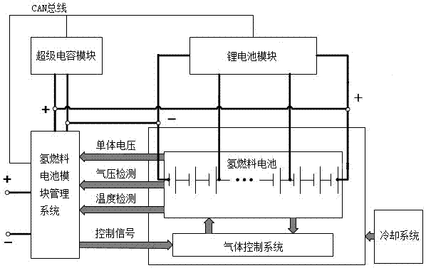
[0021] Such as figure 1 As shown, the new energy vehicle drive system based on composite hydrogen fuel and lithium-ion battery includes supercapacitor module, hydrogen fuel cell module management system, hydrogen fuel cell, gas control system and lithium battery module.

[0022] The output end of the hydrogen fuel cell is connected to the charging input end of the lithium battery module, so that the hydrogen fuel cell can continuously charge the lithium battery module.

[0023] The anode of the hydrogen fuel cell is connected in parallel to the positive common connection point of the supercapacitor module and the hydrogen fuel cell module management system, and the negative pole of the hydrogen fuel cell is connected in parallel to the nega...


PUM


Abstract

The invention discloses a new energy automobile driving system based on a composite hydrogen fuel and lithium ion battery. The new energy automobile driving system based on the composite hydrogen fueland lithium ion battery comprises a supercapacitor module, a hydrogen fuel battery module management system, a hydrogen fuel battery, a gas control system and a lithium battery module; an output endof the hydrogen fuel battery is connected with a charging input end of the lithium battery module; the anode and the cathode of the hydrogen fuel battery are respectively connected to the anode publicconnection point and the cathode public connection point of the supercapacitor module and the hydrogen fuel battery module management system in parallel; the lithium battery module and the supercapacitor module are respectively connected with a sampling signal input end of the hydrogen fuel battery module management system through a bus; and a control signal output end of the hydrogen fuel battery module management system is connected with the gas control system of the hydrogen fuel battery. The invention relates to the technical field of hybrid drive, can reflect the dynamic situation of thehydrogen fuel battery in real time and can improve the durability performances of the hydrogen fuel battery and the lithium battery. And by using the method, reasonable electric energy distribution between the hydrogen fuel battery and the lithium battery is realized.

Description

technical field [0001] The invention relates to a new energy vehicle drive system based on composite hydrogen fuel and lithium ion battery. Background technique [0002] The widespread use of new energy by human beings has led to the rapid expansion of the secondary battery market. In the current new energy system, the requirements for secondary batteries are ubiquitous. Whether it is electric vehicles, wind energy, solar grid connection or grid peak shaving, there is an urgent need for a cheap, reliable, safe and long-life secondary battery. The secondary batteries currently developed are mainly concentrated in lithium-ion batteries, high-temperature sodium-sulfur batteries, sodium-nickel-chloride batteries and vanadium flow batteries. These batteries have their own advantages, such as long life and high energy density of lithium-ion batteries and high-temperature sodium-sulfur batteries, and vanadium redox flow batteries have theoretically unlimited life. But no matter ...

Claims


Application Information

Patent Timeline
Patent Type & Authority Applications(China)
IPC IPC(8): B60L11/18B60L11/00H01M8/04089H01M8/04694H01M8/0432H01M8/0438H01M8/04537H01M8/0606H01M8/04007H01M8/1007
CPCB60L50/40B60L50/72B60L58/30B60L58/33B60L58/40H01M8/04007H01M8/04104H01M8/0432H01M8/0438H01M8/04552H01M8/04656H01M8/04694H01M8/04753H01M8/0606H01M8/1007H01M2250/20Y02E60/50Y02T10/70Y02T90/40
Inventor 李玉琴刘光代
Owner 成都因纳维特科技有限公司
Learn More