
Discarded type sleeve cutterhead

It is a technology of discarding and set cutters, which is applied in the direction of milling cutters, manufacturing tools, metal processing equipment, etc., and can solve problems such as high production costs, unstable blanks, and poor outer surface finish.

Inactive Publication Date: 2018-05-01
上海泰锋精密刀具有限公司
View PDF9 Cites 1 Cited by
  • Summary
  • Abstract
  • Description
  • Claims
  • Application Information

AI Technical Summary

Problems solved by technology

[0002] The existing blades are mainly fixed on the handle by welding. After using for a period of time, once the cutting edge of the blade is worn out, the entire blade cannot be used anymore, which wastes resources; high
[0003] Ordinary sets of cutters have a 4-blade symmetrical structure. When the machining allowance is large, due to the instability of the rough blank, it is easy to cause knife vibration, resulting in poor smoothness and unstable dimensions of the processed outer circle.

Method used


Image

  • Discarded type sleeve cutterhead
  • Discarded type sleeve cutterhead
  • Discarded type sleeve cutterhead

Examples


Embodiment Construction

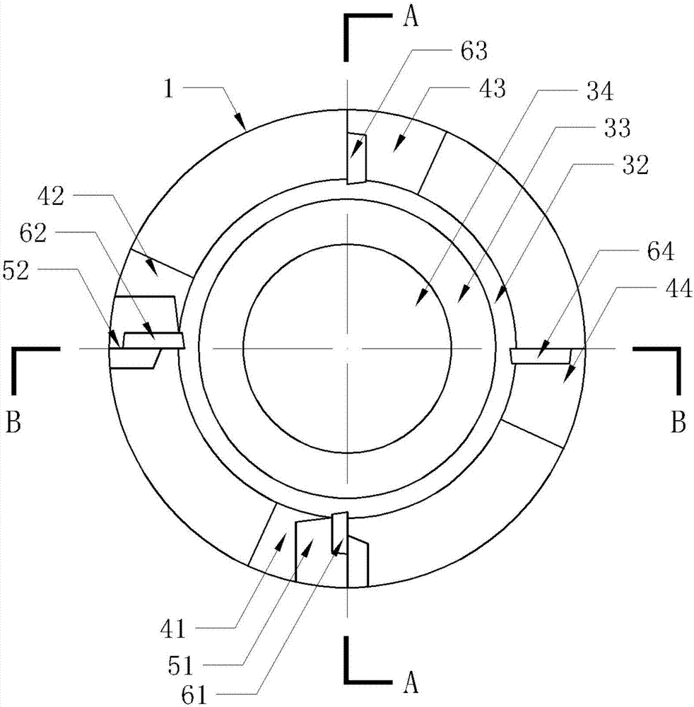
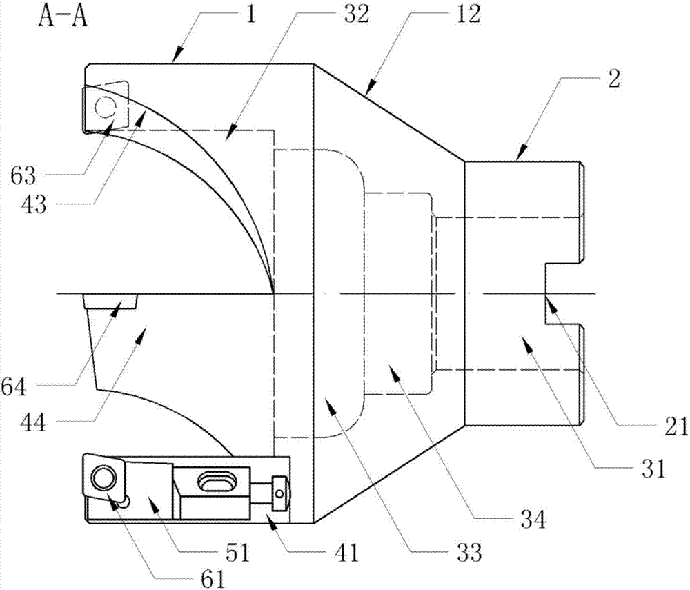
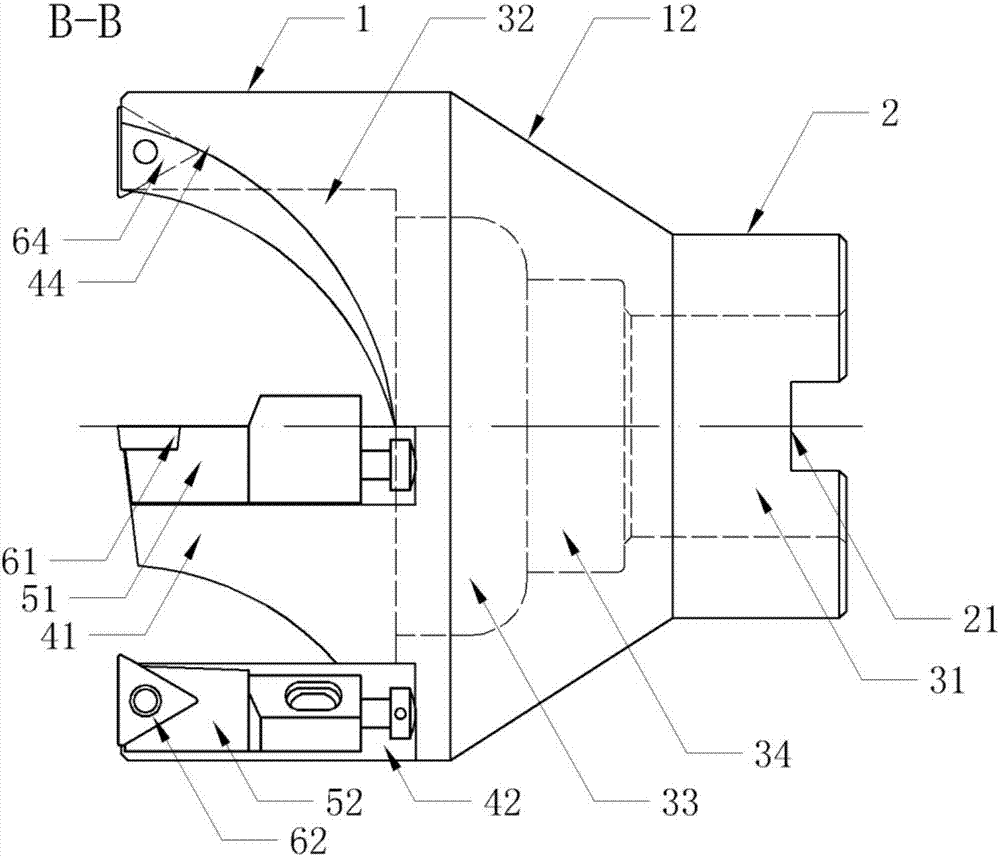
[0014] Such as Figure 1 to Figure 3 As shown, the present invention proposes a discarded cutter set, including a cutter head 1, a knife handle 2, two tool holders and four blades.

[0015] Specifically, a transitional hypotenuse 12 is provided between the cutter head 1 and the knife handle 2; the end surface of the knife handle 2 is provided with a first hole 31 for installing a milling cutter handle, and the end surface of the knife handle 2 is provided with Groove 21 installed in cooperation with the milling tool shank; the end surface of the cutter head 1 is provided with a second hole 32 for receiving chips, and chip removal is performed while processing, and the bottom end of the second hole 32 is provided with There is a third hole 33 to avoid the interference of parts, which reduces the interference to parts and improves the machining accuracy; further, in this embodiment, the preferred solution is: the cutter head 1 and the knife handle 2 are integrally structured, an...


PUM


Abstract

The invention provides a discarded type sleeve cutterhead. The discarded type sleeve cutterhead comprises a cutterhead body, a cutter handle, cutter clamps and cutter blades; a transitional bevel edgeis arranged between the cutterhead body and the cutter handle; the end face of the cutter handle is provided with a first hole groove used for mounting a milling cutter handle, and a groove is formedin the end face of the cutter handle, and the milling cutter handle and the groove are mounted in a matched mode; the end face of the cutterhead body is provided with a second hole groove for accommodating cutting chippings, and the bottom end of the second hole groove is provided with a third hole groove for avoiding interference of parts; the end face of the cutterhead body is provided with four protrusion parts, the cutter blade is locked and fixed to the corresponding pair of adjacent protrusion parts, the cutter clamps are mounted on the other pair of adjacent protrusion parts, and the cutter blades are locked and fixed to the cutter clamps; and an included angle of the cutting faces of the adjacent cutter blades is 90 degrees, the cutting edges of the cutter blades are located on the same plane and perpendicular to the axis of the cutterhead body. The discarded type sleeve cutterhead adopts fixed and floating blade edge design, the cutter blades fixed to the cutterhead body canbear large cutting force, the size cannot be adjusted, and the cutter clamps can avoid the situations of vibration edge, poor finish degree and the unstable workpiece size due to uniformity of blank oxide skin by adjusting the size.

Description

technical field [0001] The invention relates to a cutting tool, in particular to a discarded set cutter head. Background technique [0002] The existing blades are mainly fixed on the handle by welding. After using for a period of time, once the cutting edge of the blade is worn out, the whole blade can no longer be used, which wastes resources; high. [0003] Ordinary sets of cutters have a 4-blade symmetrical structure. When the machining allowance is large, due to the instability of the rough blank, it is easy to cause knife vibration, resulting in poor finish and unstable dimensions of the processed outer circle. Contents of the invention [0004] The object of the present invention is to provide a discarded cutterhead which can adjust the blade by an adjustable holder to avoid edge vibration. [0005] In order to achieve the above object, the present invention proposes a discarded cutter head, including a cutter head, a knife handle, a knife holder and a blade; a tr...

Claims


Application Information

Patent Timeline
Patent Type & Authority Applications(China)
IPC IPC(8): B23C5/08B23C5/24
CPCB23C5/08B23C5/24
Inventor 盛胜利
Owner 上海泰锋精密刀具有限公司
Learn More