
Solid-state direct current overcurrent protection circuit

An overcurrent protection circuit, DC power supply technology, applied in emergency protection circuit devices, protections that respond to overcurrent, circuit devices, etc. The effect of short action time, easy calculation of parameters and fast response speed

Pending Publication Date: 2018-04-27
PANZHIHUA UNIV
View PDF8 Cites 2 Cited by
  • Summary
  • Abstract
  • Description
  • Claims
  • Application Information

AI Technical Summary

Problems solved by technology

[0003] The defects of the above schemes are: 1. Air switch: because it is a mechanical structure, an arc may be generated when tripping, so frequent protection actions will greatly reduce the life of the air switch
2. Use a switching power supply chip with overcurrent protection for power supply design: the structure is complex, and a large number of calculations are required for each design
3. Series fuse: The fuse is a one-time use component, and it will be scrapped every time the protection action is used, which is uneconomical
4 Self-recovery fuse: It is a good alternative to traditional fuses, but the withstand voltage is not high, and it is very limited in high-voltage and high-power occasions
[0004] Generally speaking, the above schemes all have the problem of low flexibility. Every time the parameters are changed, they must be redesigned, or even replaced with different types of components, which brings great inconvenience to users.

Method used


Image

  • Solid-state direct current overcurrent protection circuit
  • Solid-state direct current overcurrent protection circuit

Examples


Embodiment Construction

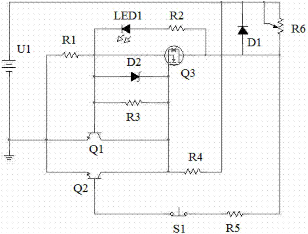
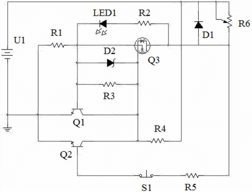
[0015] Such as figure 1 As shown in the solid-state DC overcurrent protection circuit of the present invention, the positive pole of the DC power supply U1 is connected to the negative pole of the freewheeling diode D1 and one end of the load R6. The load R6 can be an adjustable resistor, and the other end of the load R6 is connected to the base of the second NPN transistor Q2 through the series current limiting resistor R5 and the recovery switch S1, and the collector of the second NPN transistor Q2 is connected to the DC through the pull-up resistor R4. Positive connection for power supply U1. The recovery switch S1 is a normally closed non-self-locking switch, which is used to restore the conduction of the protection circuit when pressed. The emitter of the second NPN transistor Q2 is connected to the gate of the switch tube Q3 of MOSFET transistor or IGBT transistor type through the sampling resistor R1, and the drain of the switch tube Q3 is connected to the anode of the...


PUM


Abstract

The invention relates to a solid-state direct current overcurrent protection circuit. A direct current power supply is connected with the negative pole of a free-wheeling diode and one end of a load.The other end of the load is connected with the base of a second NPN transistor through a current limiting resistor and a recovery switch, wherein the current limiting resistor and the recovery switchare connected in series. The collector of the second NPN transistor is connected with the direct current power supply through a pull-up resistor. The emitter of the second NPN transistor is connectedwith the gate of a switch tube of the transistor type through a sampling resistor, and is connected with the positive pole of the free-wheeling diode and the other end of the load through the drain of the switch tube. The drain of the switch tube is connected with the base of a first NPN transistor. The emitter of the first NPN transistor is connected with the negative pole of the direct currentpower supply, and the collector is connected with the source of the switch tube. A zener diode and pull-down resistor, which are parallel, are arranged between the base of the first NPN transistor andthe source of the switch tube. According to the invention, the solid-state direct current overcurrent protection circuit has the advantages of simple structure, wide applicable voltage range and short operation time, can be redesigned according to actual occasions by flexibly changing parameters, and has a self-locking function.

Description

technical field [0001] The invention relates to a circuit structure, in particular to a solid-state direct current overcurrent protection circuit. Background technique [0002] At present, many power supply products have over-current protection function, which reflects the important position of over-current protection in power supply safety. The existing over-current protection methods mainly include: 1. Use air switches. 2. Use a switching power supply chip with overcurrent protection for power supply design. 3. Connect the fuse in series. 4 series self-recovery fuses. [0003] The disadvantages of the above schemes are: 1. Air switch: because it is a mechanical structure, an arc may be generated when tripping, so frequent protection actions will greatly reduce the life of the air switch. 2. Use a switching power supply chip with overcurrent protection for power supply design: the structure is complex, and a large number of calculations are required for each design. 3. ...

Claims


Application Information

Patent Timeline
Patent Type & Authority Applications(China)
IPC IPC(8): H02H3/08
CPCH02H3/087
Inventor 刘晨于娟白浪王磊
Owner PANZHIHUA UNIV
Learn More