
Antenna vibrator

An antenna vibrator and vibrator technology, applied in the directions of antenna support/installation device, radiating element structure, etc., can solve the problems of complex processing technology of base and vibrator main body, inconvenient line installation, narrow frequency band of antenna vibrator, etc. Welding, reducing weight, increasing the effect of parameters

Pending Publication Date: 2018-04-27
GUANGDONG SHENGLU TELECOMM TECH
View PDF4 Cites 5 Cited by
  • Summary
  • Abstract
  • Description
  • Claims
  • Application Information

AI Technical Summary

Problems solved by technology

[0002] At present, there are various types of antennas, which are widely used in wireless communication fields such as mobile phones, automobiles, and computers. The dual-polarized antenna oscillators used in general mobile communication base station antennas are mainly composed of a base and a vibrator body fixed on the base. Composition, the base is a circular base, usually made of metal copper, the main body of the vibrator and the base are connected by welding, and the structure is firm. The disadvantage of this structure is that the accuracy cannot meet the requirements at high frequencies, and the anti-interference ability is weak. The main body of the vibrator has complex processing technology, inconvenient wiring installation, and high manufacturing cost
The other is a printed board type vibrator. The frequency band of this antenna vibrator is too narrow. Although the bandwidth can be increased by adding one or more layers of parasitic sheet technology, the bandwidth is still not enough, and the use of line installation in the array at high frequencies is not enough. Convenient, and radiation efficiency is relatively low at high frequencies

Method used


Image

  • Antenna vibrator
  • Antenna vibrator
  • Antenna vibrator

Examples


Embodiment Construction

[0016] The technical solution will be described in detail below in conjunction with specific embodiments.

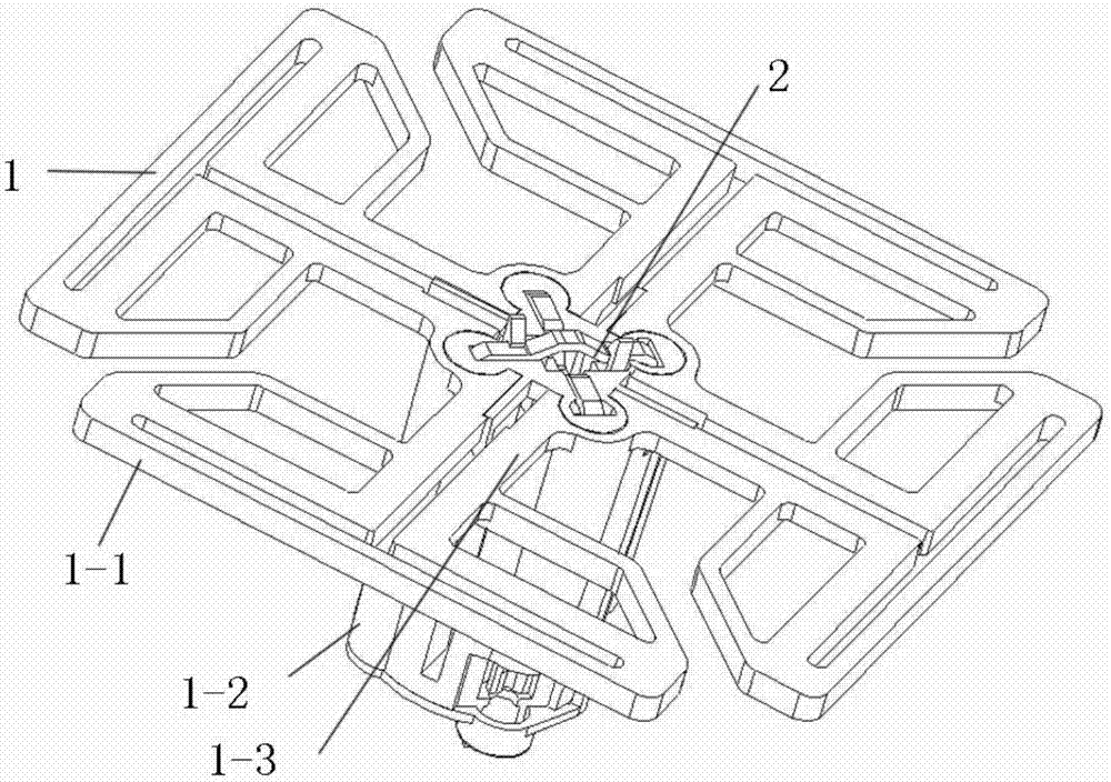
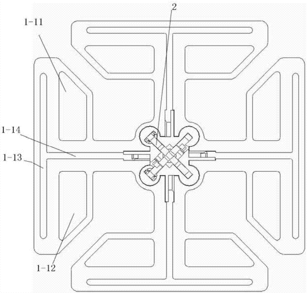
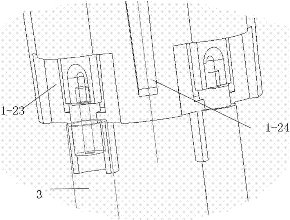
[0017] Such as Figure 1-Figure 4 As shown, the present invention is an antenna vibrator, which includes a vibrator main body 1 and a feeding sheet 2. The vibrator main body includes four groups of radiation sheets 1-1, balun holders 1-2, and the gap between the radiation sheet and the balun holders Connected with the vibrator connecting arm 1-3, the radiation sheet is hollowed out with left and right hollow holes 1-11, 1-12 and strip hole 1-13, and the vibrator connecting arm is hollowed out with a strip vertically connected to the strip hole. Hole 2 1-14, the left and right hollow holes are symmetrically arranged on both sides of the strip hole 2, thus forming a current loop, the equivalent vibrator arm is longer, and the gain is higher than the conventional vibrator. The balun fixing seat 1-2 includes a base 1-21 and four feeding balun supporting columns 1-22, one en...


PUM


Abstract

The invention discloses an antenna vibrator. The antenna vibrator is characterized in that the antenna vibrator comprises a vibrator body and a feeding slice; the vibrator body comprises four radiation slices and a balun fixing base; vibrator connecting arms are connected between the radiation slices and the balun fixing base; left and right hollow holes and a first bar-shaped hole are hollowed out in each radiation slice; a second bar-shaped hole which is vertically connected with a first bar-shaped hole is hollowed out in each vibrator connecting arm; and left and right hollow holes are symmetrically arranged on both sides of the second bar-shaped holes. According to the invention, the antenna vibrator has the advantages of simple structure, low cost, firm cable welding, increased bandwidth and enhanced structural strength.

Description

technical field [0001] The invention relates to the technical field of communication equipment, in particular to an antenna dipole. Background technique [0002] At present, there are various types of antennas, which are widely used in wireless communication fields such as mobile phones, automobiles, and computers. The dual-polarized antenna oscillators used in general mobile communication base station antennas are mainly composed of a base and a vibrator body fixed on the base. Composition, the base is a circular base, usually made of metal copper, the main body of the vibrator and the base are connected by welding, and the structure is firm. The disadvantage of this structure is that the accuracy cannot meet the requirements at high frequencies, and the anti-interference ability is weak. The main body of the vibrator has complex processing technology, inconvenient wiring installation, and high manufacturing cost. The other is a printed board type vibrator. The frequency b...

Claims


Application Information

Patent Timeline
Patent Type & Authority Applications(China)
IPC IPC(8): H01Q1/36H01Q1/12
CPCH01Q1/12H01Q1/36
Inventor 但从锐谢武文邓碧波杨华方雄波朱强
Owner GUANGDONG SHENGLU TELECOMM TECH
Learn More