Environment-friendly vapor heat exchanger capable of achieving fast heat exchange and operation method of environment-friendly vapor heat exchanger

An environmentally friendly, heat exchanger technology, used in steam/steam condensers, lighting and heating equipment, etc., can solve the problems of affecting the processing process, cooling, and time-consuming, and achieve the effect of accelerating the heating speed and improving the evaporation rate.

Active Publication Date: 2018-04-27
ZHEJIANG BIJING ENVIRONMENTAL PROTECTION TECH CO LTD
View PDF5 Cites 0 Cited by
  • Summary
  • Abstract
  • Description
  • Claims
  • Application Information

AI Technical Summary

Problems solved by technology

[0004] Aiming at the deficiencies of the prior art, the present invention provides an environmentally friendly steam heat exchanger capable of rapid heat exchange and its operation method, which solves the problem that the existing steam heat exchanger only heats water to evaporate it, and the evaporation speed is slow , the heating rate of the liquid is low and takes a long time, which affects the processing process, and the existing steam heat exchanger is not convenient to monitor the temperature of the liquid after the liquid is heated. When the temperature of the liquid is too high, the liquid cannot be heated in time. Cooling, problems affecting liquid processing and production

Method used


Image

  • Environment-friendly vapor heat exchanger capable of achieving fast heat exchange and operation method of environment-friendly vapor heat exchanger
  • Environment-friendly vapor heat exchanger capable of achieving fast heat exchange and operation method of environment-friendly vapor heat exchanger
  • Environment-friendly vapor heat exchanger capable of achieving fast heat exchange and operation method of environment-friendly vapor heat exchanger

Examples


Embodiment Construction

[0032] The following will clearly and completely describe the technical solutions in the embodiments of the present invention with reference to the accompanying drawings in the embodiments of the present invention. Obviously, the described embodiments are only some, not all, embodiments of the present invention. Based on the embodiments of the present invention, all other embodiments obtained by persons of ordinary skill in the art without making creative efforts belong to the protection scope of the present invention.

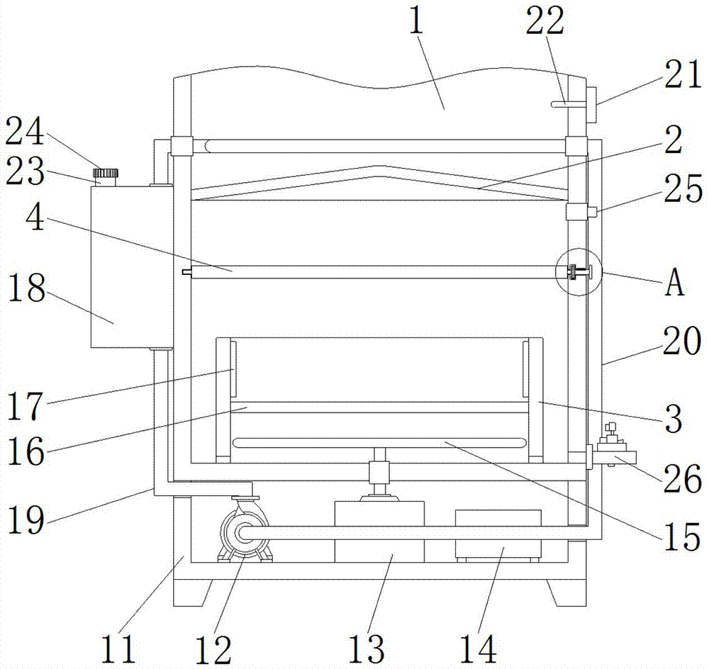
[0033] see Figure 1-3, the present invention provides a technical solution: an environmentally friendly steam heat exchanger capable of rapid heat exchange, including a box body 1, the bottom of the box body 1 is fixedly installed with a cabinet 11, and the inside of the cabinet 11 is fixed and installed sequentially from left to right There are a water pump 12, a heater 13 and an ultrasonic atomizer 14. The ultrasonic atomizer 14 emits ultrasonic waves into ...


PUM


Abstract

The invention discloses an environment-friendly vapor heat exchanger capable of achieving fast heat exchange. The environment-friendly vapor heat exchanger comprises a box body. A bottom plate is fixedly mounted in the box body. A water tank is fixedly mounted at the bottom of an inner cavity of the box body. A first baffle and second baffles are sequentially and rotationally connected to the position, located between the bottom plate and the water tank, in the box body from front to back. A first gear and second gears are fixedly mounted at the positions, located in the right wall of the boxbody, of the right side of the first baffle and the right sides of the second baffles correspondingly. One side of the first gear is engaged with the second gears. The right side of the first gear isfixedly connected with a rotary shaft. The invention relates to the technical field of vapor heat exchangers. According to the environment-friendly vapor heat exchanger capable of achieving fast heatexchange and an operation method of the environment-friendly vapor heat exchanger, after the first baffle is rotated, the second baffles can be rotated at the same time through engagement of one sideof the first gear and the second gears, the multiple second baffles are arranged, vapor can be blocked by the first baffle and the second baffles after rotating, the vapor is prevented from continuingto heat the bottom plate, and the environment-friendly vapor heat exchanger is used for assisting in cooling.

Description

technical field [0001] The invention relates to the technical field of steam heat exchangers, in particular to an environment-friendly steam heat exchanger capable of rapid heat exchange and an operation method thereof. Background technique [0002] A heat exchanger is a device that transfers part of the heat of a hot fluid to a cold fluid, also known as a heat exchanger. Heat exchangers play an important role in chemical, petroleum, power, food and many other industrial productions. In chemical production, heat exchangers can be used as heaters, coolers, condensers, evaporators and reboilers, etc., and are widely used A heat exchanger is an energy-saving device that transfers heat between materials between two or more fluids at different temperatures. It transfers heat from a fluid with a higher temperature to a fluid with a lower temperature, so that the fluid temperature reaches the process The specified index is to meet the needs of the process conditions, and it is als...

Claims


Application Information

Patent Timeline
Patent Type & Authority Applications(China)
IPC IPC(8): F28B1/02F28B9/04
CPCF28B1/02F28B9/04
Inventor 李先明李何栋张钦波朱菊林
Owner ZHEJIANG BIJING ENVIRONMENTAL PROTECTION TECH CO LTD
Why Eureka
Try Eureka