Sealing structure between stator and rotor of aero-engine

A technology for aero-engines and rotors, which is applied to engine components, machines/engines, mechanical equipment, etc. It can solve the problems of immature honeycomb and grate tooth repair technology and difficult maintenance, and achieve easy disassembly and maintenance and long service life , the effect of reducing leakage

Inactive Publication Date: 2018-04-27
SHENYANG LIMING AERO-ENGINE GROUP CORPORATION
View PDF8 Cites 1 Cited by
  • Summary
  • Abstract
  • Description
  • Claims
  • Application Information

AI Technical Summary

Problems solved by technology

At present, the maintenance of the sealing structure is relatively difficult, and the repair technology of honeycomb and grate teeth is not mature enough

Method used


Image

  • Sealing structure between stator and rotor of aero-engine
  • Sealing structure between stator and rotor of aero-engine

Examples


Embodiment Construction

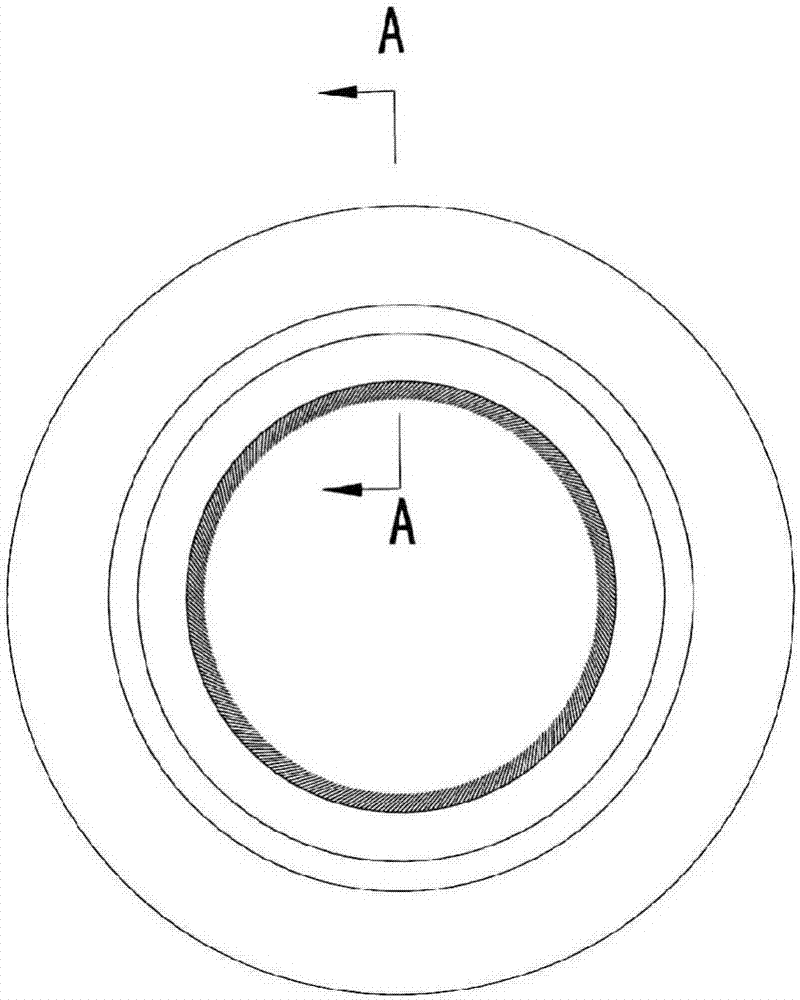
[0013] Such as figure 1 and figure 2 As shown, the sealing structure between the static rotors of an aero-engine of the present invention is in the form of a ring as a whole, and is fixed on the stator part 7 by a circle of screws 9 and a baffle 8, which is convenient for disassembly and maintenance. It specifically includes: an annular mandrel 1 , a brush wire 2 , a hoop 3 , an annular pressing plate 4 and an annular supporting plate 5 .

[0014] Multiple strands of the brush filaments 2 are wound on the annular mandrel 1 , and the ends of the brush filaments 2 face the inner side of the annular mandrel 1 . The hoop 3 is bent into an arc to fix the brush filament 2 on the annular mandrel 1 . The annular pressing plate 4 and the annular supporting plate 5 are assembled together to form an annular cavity, and an annular notch is formed on the inner peripheral surface of the annular cavity. The annular mandrel 1, the brush filament 2 and the hoop 3 are assembled in the annul...


PUM


Abstract

The invention relates to a sealing structure between a stator and a rotor of an aero-engine. The sealing structure is fixed on a stator piece and comprises an annular mandrel, brushing wires, a hoop ring, an annular pressing plate and an annular supporting plate; the multiple strands of brushing wires are wounded around the annular mandrel, the tail ends of the brushing wires face the inner side of the annular mandrel, the hoop ring is bent into an arc shape to fix the brushing wires on the annular mandrel, and the annular supporting plate and the annular pressing plate are assembled togetherto form an annular cavity; and an annular groove opening is formed in the inner circumferential surface of the annular cavity, the annular mandrel, the brushing wires and the hoop ring are assembled in the annular cavity, and the brushing wires stretch out from the annular groove opening. According to the sealing structure between the stator and the rotor of the aero-engine, the air leakage rate between the rotor and the stator can be effectively reduced, performance of the engine original design state is kept, and safety and reliability of engine work are improved.

Description

technical field [0001] The invention relates to a sealing mechanism, in particular to a sealing structure between stationary rotors of an aero-engine. Background technique [0002] At present, most of the sealing between rotor and stator of aero-engine adopts the sealing structure of grate tooth and layer type, or adopts the sealing structure of grate tooth and honeycomb type. In the traditional sealing structure, the coating or honeycomb is sprayed or welded on the stator part, and the grate tooth is the rotor part. In order to improve the hardness of the grate tooth tip, the wear-resistant coating is sprayed on the grate tooth tip. When the engine is not working, there is a certain gap between the coating or honeycomb and the grate; when the engine is working, the coating or honeycomb and the grate move relative to each other, and due to centrifugal force, there will be contact between the coating or honeycomb and the grate. Through contact, the sealing between the static...

Claims


Application Information

Patent Timeline
Patent Type & Authority Applications(China)
IPC IPC(8): F02C7/28F01D11/12
CPCF02C7/28F01D11/127
Inventor 郭颖韦周庆王凯王志哲赵铁军
Owner SHENYANG LIMING AERO-ENGINE GROUP CORPORATION
Why Eureka
Try Eureka