
Building bar derusting device with good derusting effect

A technology for construction and steel bars, which is applied in the direction of grinding/polishing safety devices, grinding workpiece supports, grinding machines, etc. It can solve the problems of affecting the practicability of steel bars, affecting the use of steel bars, and the linear decline in the bearing capacity of steel bars, so as to improve rust removal Effect, the effect of speeding up the rust removal speed

Inactive Publication Date: 2018-04-27
ZHENGZHOU CHENGHE INFORMATION TECH CO LTD
View PDF5 Cites 9 Cited by
  • Summary
  • Abstract
  • Description
  • Claims
  • Application Information

AI Technical Summary

Problems solved by technology

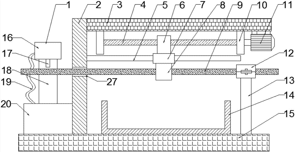
The application of steel bars is very important in the stability of building structures. However, because steel bars are made of steel, if they are exposed to the air for a long time, their surfaces are easily oxidized by air and rust, and the rust of steel bars will reduce the cross-section of steel bars. , resulting in a straight drop in the bearing capacity of the steel bar, which greatly affects the practicability of the steel bar; if the rust is not treated, it will affect the use of the steel bar. When manually derusting the steel bar, it is time-consuming and laborious, and it is easy to be injured during the derusting process. Existing derusting machines are complicated to operate and cannot collect and utilize iron rust, which has a wide range of applications; therefore, we need a derusting device for steel bars with good derusting effect

Method used


Image

  • Building bar derusting device with good derusting effect
  • Building bar derusting device with good derusting effect
  • Building bar derusting device with good derusting effect

Examples


Embodiment Construction

[0016] The technical solution of this patent will be further described in detail below in conjunction with specific embodiments.

[0017] Embodiments of the present patent are described in detail below, examples of which are shown in the drawings, wherein the same or similar reference numerals designate the same or similar elements or elements having the same or similar functions throughout. The embodiments described below by referring to the figures are exemplary and are only used for explaining the patent, and should not be construed as limiting the patent.

[0018] In the description of this patent, it is to be understood that the terms "center", "upper", "lower", "front", "rear", "left", "right", "vertical", "horizontal", The orientation or positional relationship indicated by "top", "bottom", "inner", "outer", etc. is based on the orientation or positional relationship shown in the drawings, and is only for the convenience of describing this patent and simplifying the des...


PUM


Abstract

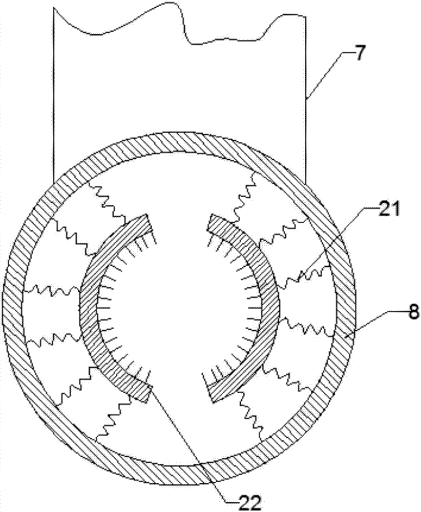
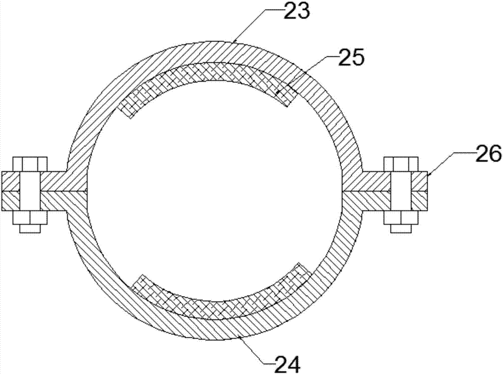
The invention discloses a building bar derusting device with a good derusting effect, and belongs to the field of building equipment. The building bar derusting device comprises a bottom plate, wherein a liquid containing box is arranged just below a nozzle, the liquid containing box is fixed to the upper surface of the bottom plate, and the liquid containing box is connected with an input port ofa liquid pump through a liquid draining pipe; a left side plate is vertically arranged on the left side of a spray device, and the left side plate is fixedly connected with the bottom plate; two mounting plates are respectively arranged on the left and right sides of the lower end surface of a top plate; a driving motor is fixedly arranged on the right side of the lower end surface of the top plate by virtue of a bracket, and an output shaft of the driving motor is connected with a screw rod; and a screw rod sleeve is arranged on the screw rod and is movably connected with the screw rod. Thebuilding bar derusting device has the advantage of reasonable structural design; two steel wire brushes are symmetrically arranged in an annular block, so that bars can be derusted all round; and auxiliary derusting liquid is sprayed to the bars by the spray device before the bars enter the derusting device, so that the bar derusting speed is increased, and additionally, the bar derusting effect is increased.

Description

technical field [0001] The invention relates to the field of construction equipment, in particular to a derusting device for steel bars used in construction with good derusting effect. Background technique [0002] Steel bars are widely used in the field of construction, especially in large, heavy, light thin-walled and high-rise building structures. The application of steel bars is very important in the stability of building structures. However, because steel bars are made of steel, if they are exposed to the air for a long time, their surfaces are easily oxidized by air and rust, and the rust of steel bars will reduce the cross-section of steel bars. , resulting in a straight drop in the bearing capacity of the steel bar, which greatly affects the practicability of the steel bar; if the rust is not treated, it will affect the use of the steel bar. When manually derusting the steel bar, it is time-consuming and laborious, and it is easy to be injured during the derusting pr...

Claims


Application Information

Patent Timeline
IPC IPC(8): B24B27/033B24B41/06B24B55/12B24B57/02
CPCB24B27/033B24B41/067B24B55/12B24B57/02
Inventor 张强
Owner ZHENGZHOU CHENGHE INFORMATION TECH CO LTD
Learn More