
Non-contact type electromagnetic brake

An electromagnetic brake, non-contact technology, applied in the direction of electric brake/clutch, permanent magnet clutch/brake, electric components, etc., can solve the problems of high noise, high brake friction and dust pollution, large device loss, etc. Noise, the effect of solving the poor braking effect

Pending Publication Date: 2018-04-24
CHANGAN UNIV
View PDF7 Cites 1 Cited by
  • Summary
  • Abstract
  • Description
  • Claims
  • Application Information

AI Technical Summary

Problems solved by technology

[0002] At present, the existing brakes on the market are all contact brakes, which perform braking work through the friction between the brake pads and the brake disc. This type of brake device firstly produces relatively large noise due to braking, and secondly, brake friction produces The dust pollution is relatively high, and the third is that the brake friction has a large loss on the device, and the parts need to be replaced frequently, and the use cost is high. At the same time, when braking for a long time, the brake device will generate a lot of heat, resulting in poor braking effect.

Method used


Image

  • Non-contact type electromagnetic brake
  • Non-contact type electromagnetic brake
  • Non-contact type electromagnetic brake

Examples


Embodiment Construction

[0018] The present invention is further described below in conjunction with accompanying drawing:

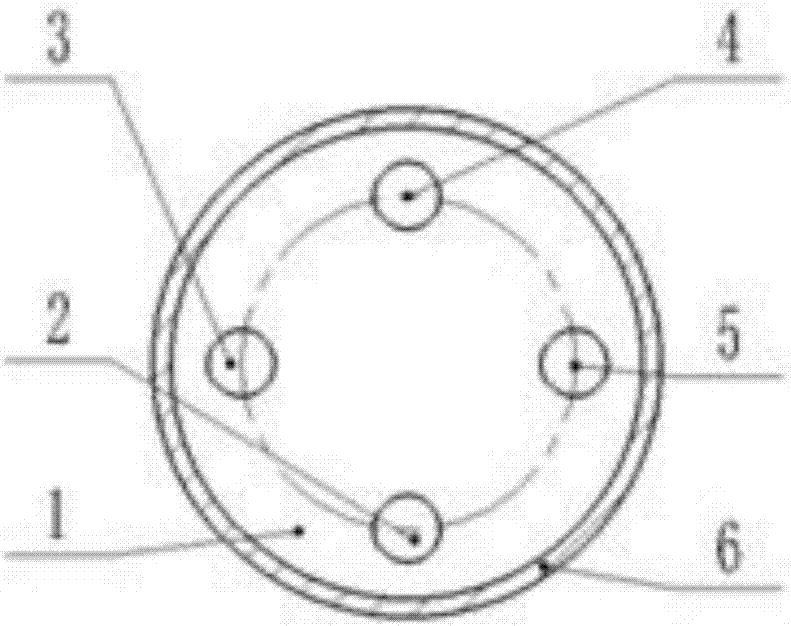
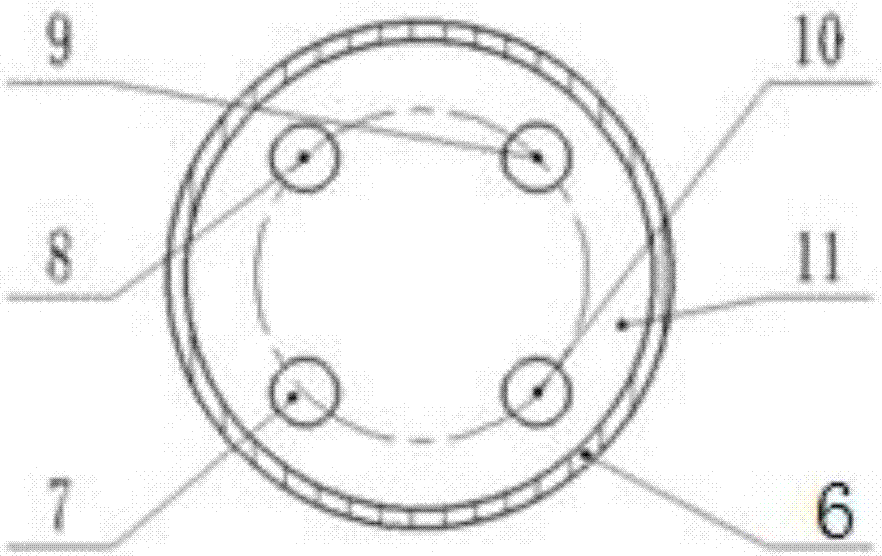
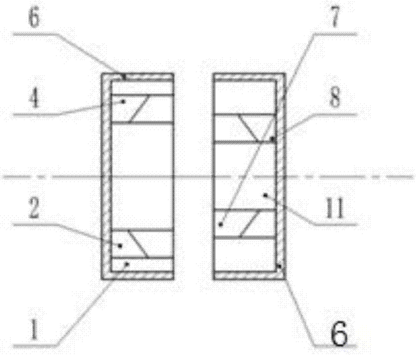
[0019] see Figure 1-Figure 4 , a non-contact electromagnetic brake, including a fixed plate 1, a moving plate 11, a fixed plate electromagnet and a moving plate electromagnet; The radian is provided with several mounting holes, and the fixed plate electromagnet is fixedly arranged in the mounting holes; the moving plate 11 is concentrically arranged on the side of the fixed plate 1 in parallel with the fixed plate 1, and there is a gap between the moving plate 11 and the fixed plate 1; The mounting holes corresponding to the fixed plate 1 are arranged on the plate 11, and the moving plate electromagnets are fixedly arranged in the mounting holes; The pole direction of the moving disk electromagnet facing the fixed disk 1 side on the disk 11 is arranged alternately, and the pole direction of the moving disk electromagnet facing the fixed disk 1 side can be changed to ensure the...


PUM


Abstract

The invention provides a non-contact type electromagnetic brake, which comprises a fixed disc, a movable disc, fixed disc electromagnets and movable disc electromagnets. The fixed disc is vertically arranged. A plurality of installation holes are formed in the fixed disc at equal radians on an arc line around the center of the fixed disc. The fixed disc electromagnets are fixedly arranged in the installation holes. The movable disc and the fixed disc are homocentrically arranged on one side of the fixed disc in parallel. A gap is reserved between the movable disc and the fixed disc. Installation holes in one-to-one correspondence with the plurality of installation holes in the fixed disc are formed in the movable disc. Movable disc electromagnets are fixedly arranged in the installation holes of the movable disc. The polarities of fixed disc electromagnets arranged on the fixed disc and configured to face one side of the movable disc are alternately arranged. The polarities of movabledisc electromagnets arranged on the movable disc and configured to face one side of the fixed disc are alternately arranged. The polarities of movable disc electromagnets configured to face one side of the fixed disc can be transformed. In this way, the stress direction of movable disc electromagnets relative to the fixed disc electromagnets is ensured to be opposite to the rotating direction of the movable disc. According to the invention, the problems of noises and dusts generated during the friction braking of a transmission brake device are solved. Meanwhile, the problem that the braking effect is poor due to long-time operation heating phenomenon during the contact type friction braking process is solved.

Description

technical field [0001] The invention belongs to the technical field of braking of rotary moving parts, and in particular relates to a non-contact electromagnetic brake. Background technique [0002] At present, the existing brakes on the market are all contact brakes, which perform braking work through the friction between the brake pads and the brake disc. This type of brake device firstly produces relatively large noise when braking, and secondly, the brake friction produces The dust pollution is relatively high, and the third is that the brake friction has a large loss on the device, and the parts need to be replaced frequently, and the use cost is high. At the same time, when braking for a long time, the brake device will generate a lot of heat, resulting in poor braking effect. Contents of the invention [0003] The object of the present invention is to provide a non-contact electromagnetic brake to solve the above problems. [0004] To achieve the above object, the ...

Claims


Application Information

Patent Timeline
Patent Type & Authority Applications(China)
IPC IPC(8): H02K49/10
CPCH02K49/108
Inventor 成建联雷宏卫雷佩王望泊赵玲瑛
Owner CHANGAN UNIV
Learn More