High-frequency transformer with heat conduction structure and manufacturing method thereof
A high-frequency transformer and heat-conducting structure technology, applied in the field of transformers, can solve the problems of large temperature gradient from the surface of the transformer to the core, high temperature inside the transformer, and poor thermal conductivity, so as to improve the external heat exchange efficiency, improve thermal performance, The effect of improving the internal thermal conductivity
- Summary
- Abstract
- Description
- Claims
- Application Information
AI Technical Summary
Problems solved by technology
Method used
Image
Examples
Embodiment 1
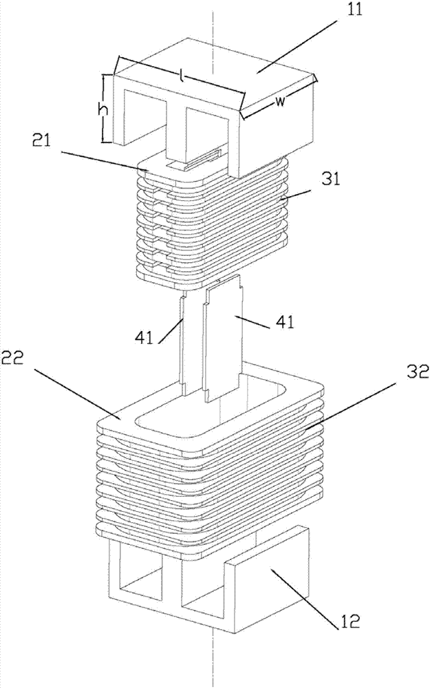
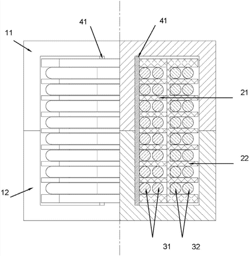
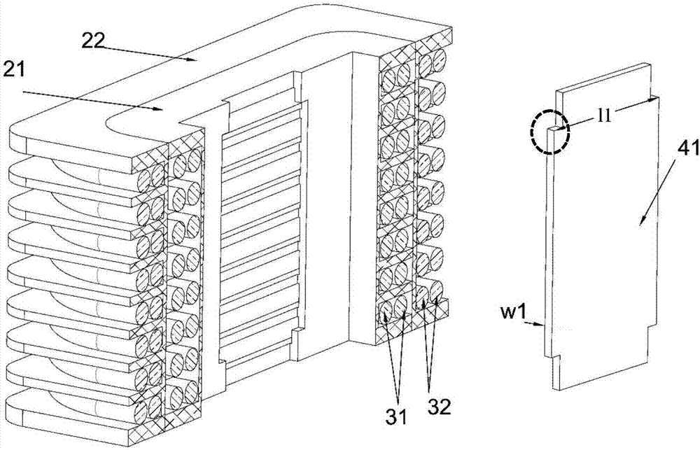
[0039] see figure 1 , figure 2 and image 3 , this embodiment is a preferred structural scheme of a high-frequency transformer with a heat-conducting structure. The high-frequency transformer is designed to have a rated power of 7.5kW, and the structure includes: a first magnetic core 11, a second magnetic core 12, and a primary winding bobbin 21 , the secondary winding skeleton 22, the primary winding 31, and the secondary winding 32.
[0040] The middle part of the primary winding bobbin 21 has a hole through it, and is used for accommodating the magnetic core leg of the first magnetic core 11 . A primary winding 31 is wound on the outer surface of the primary winding bobbin 21 . The secondary winding bobbin 22 has a hole in the middle and passes through it, for accommodating the primary winding bobbin 21 and its magnetic core legs. A secondary winding 32 is wound on the outer surface of the secondary winding bobbin 22 . That is, multiple sets of winding bobbins are se...
Embodiment 2
[0052] see Figure 4 , Figure 5 , this embodiment is a preferred structural scheme of a high-frequency transformer with a heat-conducting structure. The basic structure of the high-frequency transformer is the same as that of Embodiment 1, including: a first magnetic core 11, a second magnetic core 12, and a primary winding bobbin 21, the secondary winding skeleton 22, the primary winding 31, and the secondary winding 32.
[0053] The high-frequency transformer has a heat conduction structure inside, and the heat conduction structure includes a connected heat conduction structure and an end heat conduction structure. The connected heat conduction structure is assembled and embedded inside the winding frames 21 and 22 , and the connected heat conduction structure runs through each layer of the winding frames 21 and 22 , so it is called a connected heat conduction structure. The connected heat-conducting structure has a certain width and thickness and a specific cross-section...
Embodiment 3
[0063] see Image 6 , this embodiment is a preferred structural scheme of a high-frequency transformer with a heat-conducting structure. The basic structure of the high-frequency transformer is the same as that of Embodiment 1 and Embodiment 2, including: a first magnetic core 11, a second magnetic core 12, The primary winding bobbin 21 , the secondary winding bobbin 22 , the primary winding 31 , and the secondary winding 32 .
[0064] In this embodiment, the primary winding 31 and the secondary winding 32 are wound on two sets of primary winding bobbins 21 and secondary winding bobbins 22 respectively in a cross-winding manner. The core leg of the core 12 is wound sequentially from the inside to the outside according to the order of "primary side - secondary side - primary side - secondary side", and the winding bobbin is also in accordance with "primary side bobbin - secondary side bobbin - primary side bobbin - secondary side bobbin "The order of suits. Both the winding f...
PUM
| Property | Measurement | Unit |
|---|---|---|
| Thickness | aaaaa | aaaaa |
| Width | aaaaa | aaaaa |
| Thickness | aaaaa | aaaaa |
Abstract
Description
Claims
Application Information
 - R&D Engineer
- R&D Manager
- IP Professional
- Industry Leading Data Capabilities
- Powerful AI technology
- Patent DNA Extraction
Browse by: Latest US Patents, China's latest patents, Technical Efficacy Thesaurus, Application Domain, Technology Topic, Popular Technical Reports.
© 2024 PatSnap. All rights reserved.Legal|Privacy policy|Modern Slavery Act Transparency Statement|Sitemap|About US| Contact US: help@patsnap.com


