
Display device and electronic device

A display device and display module technology, which is applied in the fields of electrical digital data processing, instruments, digital data authentication, etc., can solve the problems of fingerprint image accuracy reduction, unfavorable thinning and thinning of electronic devices, and thick electronic devices, so as to improve user experience Effect

Active Publication Date: 2018-04-24
柳州梓博科技有限公司
View PDF12 Cites 14 Cited by
  • Summary
  • Abstract
  • Description
  • Claims
  • Application Information

AI Technical Summary

Problems solved by technology

Correspondingly, when such a larger fingerprint recognition module is combined with an electronic device (such as a mobile phone), the thickness of the electronic device will be thicker, which is not conducive to the development of the electronic device in the direction of thinning and lightening.
[0005] For the fingerprint identification module using surface light source, the accuracy of collecting the fingerprint image formed by the light emitted by the surface light source and reflected by the finger will be affected by the thickness of the glass cover , when the thickness of the glass increases, the accuracy of the fingerprint image collected due to light scattering will decrease
Correspondingly, when such a fingerprint identification module is placed under the front protective cover of the mobile phone, the fingerprint sensing accuracy of the fingerprint identification module will not be sufficient due to the thick front protective cover.

Method used


Image

  • Display device and electronic device
  • Display device and electronic device
  • Display device and electronic device

Examples


Embodiment Construction

[0059] Embodiments of the present invention are described in detail below, examples of which are shown in the drawings, wherein the same or similar reference numerals denote the same or similar elements or elements having the same or similar functions throughout. The embodiments described below by referring to the figures are exemplary only for explaining the present invention and should not be construed as limiting the present invention.

[0060] In the description of the present invention, it should be understood that the terms "first" and "second" are used for description purposes only, and cannot be interpreted as indicating or implying relative importance or implicitly indicating the quantity of indicated technical features. Thus, a feature defined as "first" or "second" may explicitly or implicitly include one or more of said features. In the description of the present invention, "plurality" means two or more, unless otherwise specifically defined.

[0061] In the descr...


PUM


Abstract

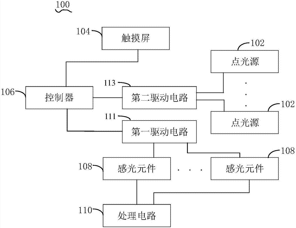
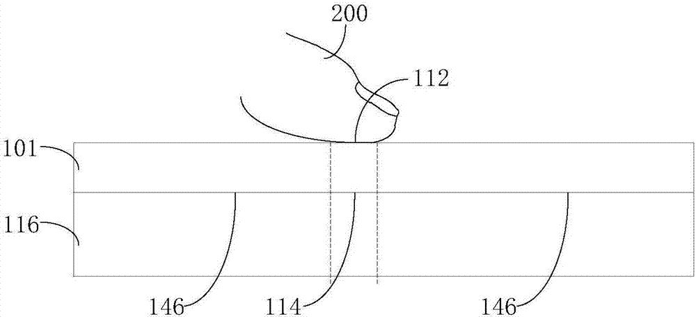
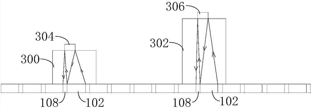
The invention discloses a display device and an electronic device. The display device is used for executing image display and is also used for executing biological characteristic information sensing.The display device comprises a plurality of point light sources, a touch screen, a controller, a plurality of photosensitive elements and a processing circuit, wherein the touch screen is used for determining the contact area of a target object on the display device; the controller is used for controlling the plurality of point light sources corresponding to the contact area to be turned on at different time to emit an optical signal to the target object; the plurality of photosensitive elements are used for receiving the optical signal reflected by the target object and converting the received optical signal into a corresponding electrical signal; and the processing circuit is used for determining the biological characteristic information of the target object according to the electrical signal. The electronic device comprises the display device.

Description

technical field [0001] The present invention relates to the field of biological feature identification, and in particular to a display device and an electronic device capable of performing full-screen biological feature information sensing. Background technique [0002] In related technologies, the principle of the optical fingerprint identification module mainly uses the reflection of light on the surface of the glass cover to identify the valley and ridge information of the fingerprint, because when the finger is pressed on the glass cover, the ridge of the fingerprint is in contact with the glass cover, and the The valley of the fingerprint is not connected with the glass cover, so that there is a large difference in the reflected light between the valley and the ridge of the fingerprint, and the reflected light is collected to realize the collection of the fingerprint. [0003] At present, optical fingerprint identification modules are mainly divided into two types, one ...

Claims


Application Information

Patent Timeline
IPC IPC(8): G06F21/32G06F3/041
CPCG06F3/0416G06F21/32G06F3/041
Inventor 李问杰
Owner 柳州梓博科技有限公司
Learn More