
FCT probe testing instrument

A technology of testing instruments and probes, which is applied in the testing field, can solve the problems of reducing detection efficiency, immovability, time-consuming and labor-intensive, etc., and achieve the effects of improving detection efficiency, reducing detection cost, and improving stability

Pending Publication Date: 2018-04-24
SUZHOU RUI AI DI AUTOMOTIVE TECH CO LTD
View PDF1 Cites 1 Cited by
  • Summary
  • Abstract
  • Description
  • Claims
  • Application Information

AI Technical Summary

Problems solved by technology

[0003] At present, the test of the special microcomputer controller for automobiles, that is, "ECU (Electronic Control Unit)" usually fixes the ECU box on the carrier board, and manually pushes the needle board with probes during the test, so that the probes are in contact with the ECU interface for testing , which greatly increases the labor intensity, is time-consuming and labor-intensive, and reduces the detection efficiency
[0004] A FCT function test fixture of Chinese Patent Application No. 201420041642.1, including a bottom box, a carrier plate, a top plate, a connecting column, an electric lifting device and a test needle, and a movable structure is set through the electric lifting device, so that the carrier plate can be lifted up and down, thereby Improve the test efficiency and make the detection stable, but the test pin is placed on the upper end of the bottom box and cannot be moved. For the different sizes of ECU boxes and the different distribution positions of the interfaces on the ECU box, it is necessary to replace the position of the test pin and the carrier board, which is not only time-consuming Laborious, but also increased costs

Method used


Image

  • FCT probe testing instrument
  • FCT probe testing instrument
  • FCT probe testing instrument

Examples


Embodiment

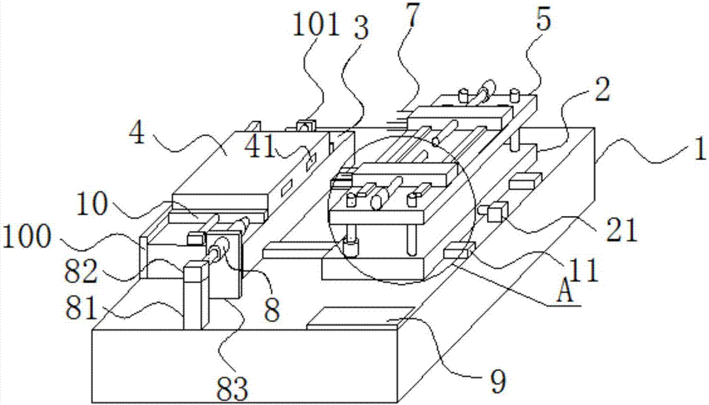
[0031] Embodiment: a kind of FCT probe test instrument, as Figure 1-Figure 4 As shown, it includes a control box 1, a movable plate 2 and a carrier plate 3, the carrier plate 3 and the movable plate 2 are all located above the control box 1, and the movable plate 2 and the carrier plate 3 are respectively Located on opposite sides of the upper surface of the control box 1;

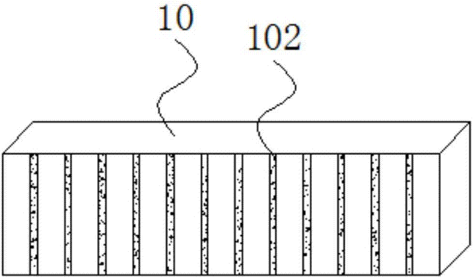
[0032] Two left and right positioning blocks 10 matching the left and right sides of the ECU box 4 are arranged on the top of the carrier plate 3, and the two positioning blocks 10 are close to or far away from each other by a clamping drive mechanism to clamp or loosen. Open the ECU box 4;

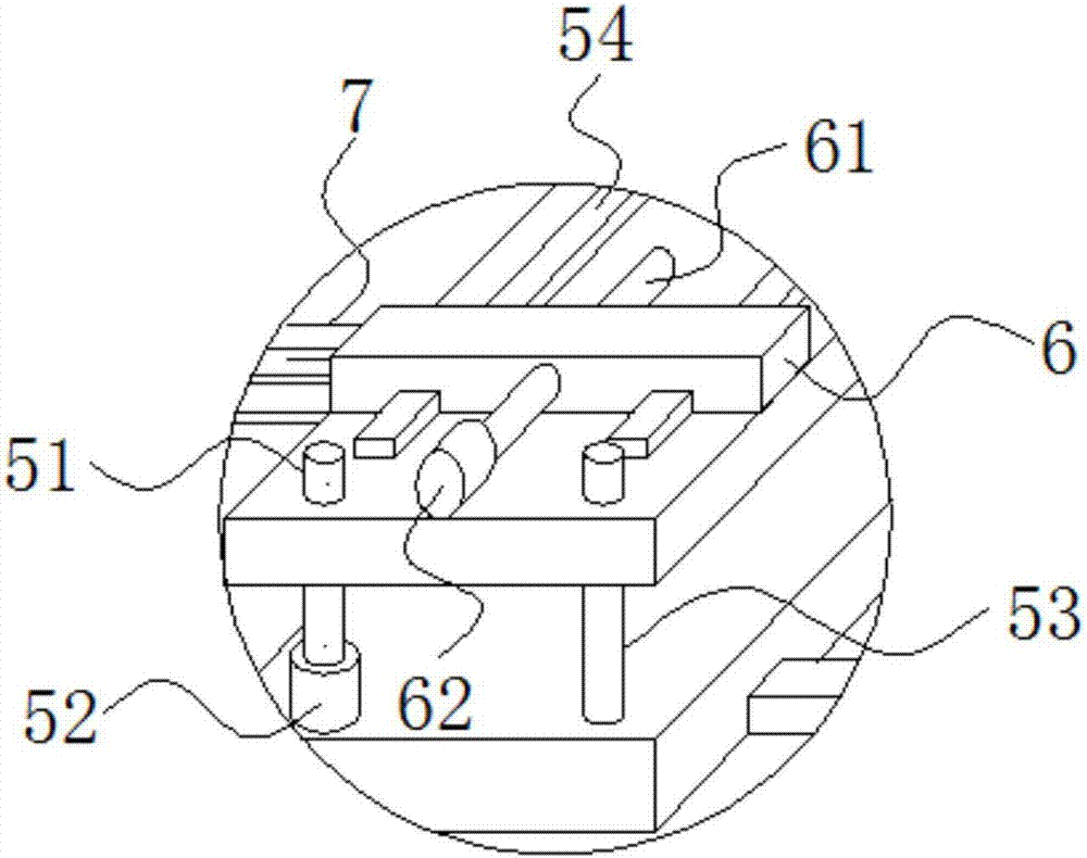
[0033] The direction of the movable plate 2 relative to the carrier plate 3 is defined as the front, the movable plate 2 is provided with a moving drive mechanism that drives it to move back and forth, the top of the movable plate 2 is provided with a needle plate 5, the The left and right sides of the needle plate...


PUM


Abstract

The invention discloses an FCT probe testing instrument, which comprises a control box, a movable plate and a carrying plate. The carrying plate and the movable plate are positioned above the controlbox. The movable plate and the carrying plate are located on the two opposite sides of the upper surface of the control box respectively. A left positioning block and a right positioning block which are matched with the left side and the right side of an ECU box are arranged above the carrying plate. The two positioning blocks get closer to each other or get further away from each other through aclamping and driving mechanism so as to clamp or loosen the ECU box. The direction of the movable plate relative to the carrying plate is defined as front. The movable plate is provided with a movabledriving mechanism for driving the movable plate to move back and forth. A needle plate is arranged above the movable plate, and lifting driving mechanisms for driving the needle plate to ascend or descend are arranged on the left side and the right side of the needle plate. According to the invention, a probe and the interface of an ECU box can be automatically connected and detected, so that thedetection efficiency is improved. ECU boxes with different sizes and interfaces at different positions on ECU boxes can be detected by the FCT probe testing instrument without the replacement of theprobe, so that the detection cost is reduced.

Description

technical field [0001] The invention belongs to the technical field of testing, in particular to an FCT probe testing instrument. Background technique [0002] FCT (Functional Test) refers to providing a simulated operating environment (stimulus and load) for the electronic control unit to be tested to make it work in various design states, so as to obtain the parameters of each state to verify the function of the electronic control board Good and bad ways to test. Simply put, it is to load the appropriate excitation on the electronic control board and measure whether the response of the output terminal meets the requirements. [0003] At present, the test of the special microcomputer controller for automobiles, that is, "ECU (Electronic Control Unit)" usually fixes the ECU box on the carrier board, and manually pushes the needle board with probes during the test, so that the probes are in contact with the ECU interface for testing , which greatly increases the labor inten...

Claims


Application Information

Patent Timeline
IPC IPC(8): G01R31/28G05B23/02
CPCG05B23/0213G01R31/2808G01R31/2818
Inventor 何佩磊邹书洋韩玉庆
Owner SUZHOU RUI AI DI AUTOMOTIVE TECH CO LTD
Learn More