
Enclosure structure with vibration suppression function and method for suppressing vibration of enclosure structure

An enclosure structure and vibration suppression technology, which is applied in the monitoring of wind turbines, the configuration of installation/supporting wind turbines, engines, etc., can solve the problems of manufacturing cost, maintenance cost increase, no obvious effect of downwind vibration, and influence on lateral vibration suppression effect and other issues, to achieve the effect of suppressing the vibration in the downwind direction

Active Publication Date: 2018-04-24
BEIJING GOLDWIND SCI & CREATION WINDPOWER EQUIP CO LTD
View PDF5 Cites 12 Cited by
  • Summary
  • Abstract
  • Description
  • Claims
  • Application Information

AI Technical Summary

Problems solved by technology

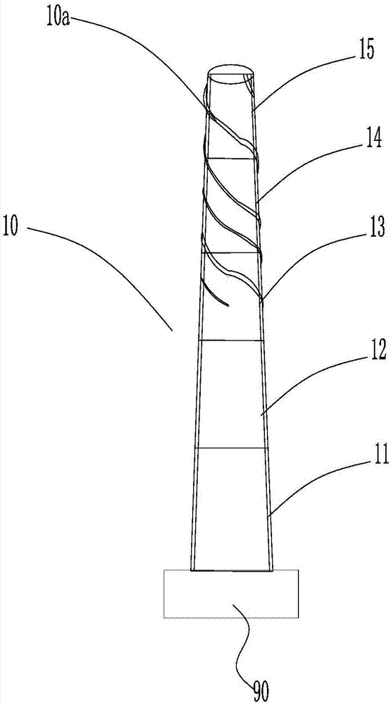
[0030] The coverage of the helix 10a (or spiral plate) on the surface of the tower will affect the effect of suppressing lateral vibration. When the coverage reaches (or exceeds) 50%, the effect of suppressing lateral vibration reaches the best, but at this time the helix 10a (or Spiral plate) and wind-induced noise of air flow have a serious impact on natural environment organisms, which are not allowed by ecological regulations; there is no obvious effect on downwind vibration;
[0031] In addition, the wind speed of the air flow will change. If the characteristic parameters (pitch, height) of the helix 10a (or spiral plate) are processed to change according to the change of the wind speed of the air flow, the corresponding manufacturing cost and maintenance cost will increase significantly.

Method used


Image

  • Enclosure structure with vibration suppression function and method for suppressing vibration of enclosure structure
  • Enclosure structure with vibration suppression function and method for suppressing vibration of enclosure structure
  • Enclosure structure with vibration suppression function and method for suppressing vibration of enclosure structure

Examples


Embodiment Construction

[0096] In order to enable those skilled in the art to better understand the technical solutions of the present invention, the present invention will be further described in detail below in conjunction with the accompanying drawings and specific embodiments.

[0097] Please refer to Figure 5 , Figure 5 It is a structural schematic diagram of the first specific embodiment of the tower with the function of suppressing vibration provided by the present invention; Figure 6 for Figure 5 Schematic diagram of skin current heating in the middle tower.

[0098] Such as Figure 5 As shown, the tower 100 is installed on the foundation 300, and the tower 100 is formed by connecting five tower sections from bottom to top, which are respectively the first tower section 101, the second tower section 102, The third tower section 103 , the fourth tower section 104 , and the fifth tower section 105 , it can be understood that the sections of the tower 100 are not limited to five sections...


PUM


Abstract

The invention discloses an enclosure structure with a vibration suppression function and a method for suppressing vibration of the enclosure structure. The outer surface of the enclosure structure isprovided with heat sources. The heat sources are used for heating an airflow boundary layer at the position of the outer surface of the enclosure structure, and through heating, the density of the airflow boundary layer rho can be lowered, the amplitude is reduced, and transverse vibration is suppressed; the airflow boundary layer at the position of the windward surface of the enclosure structureis heated, the airflow boundary layer density is lowered, and equivalently an airflow buffer layer is arranged at the windward surface; and when the windward incoming flow meets the airflow buffer layer, the turbulence can be weakened, the pulsatility is lowered, and the following wind impact on the enclosure structure is reduced, so that the following wind vibration of the enclosure structure canbe suppressed.

Description

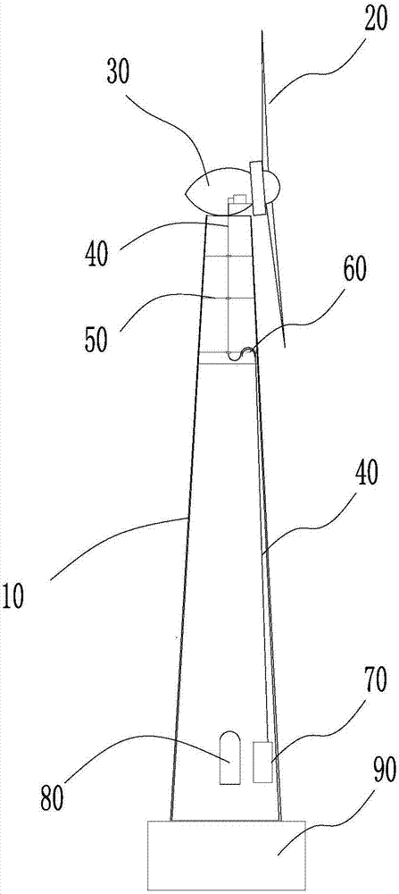
technical field [0001] The invention relates to the technical field of wind power, in particular to an enclosure structure with the function of suppressing vibration and a method for suppressing the vibration of the enclosure structure. Background technique [0002] Please refer to Picture 1-1 , Picture 1-1 Schematic diagram of wind power generation equipment. [0003] The foundation of the wind power generation equipment is the tower tube 10, which acts as a load bearing and enclosure for the whole machine. As an example, take a circular section tower tube 10 as an example. The tower tube 10 can be a steel tube, or a steel tube and a steel tube. Combination of concrete towers. The tower 10 carries the nacelle 30 of the wind power generation equipment, the generator and the wind turbine 20 . The wind power generating set composed of the tower 10, the wind turbine 20, the nacelle 30 and the generator completes the task of obtaining wind energy and converting it into elect...

Claims


Application Information

Patent Timeline
Patent Type & Authority Applications(China)
IPC IPC(8): F03D13/20F03D80/60F03D17/00F03D80/00
CPCF03D13/20F03D17/00F03D80/00F03D80/60Y02E10/72Y02E10/728
Inventor 马盛骏
Owner BEIJING GOLDWIND SCI & CREATION WINDPOWER EQUIP CO LTD
Learn More