Water-diversion-type, water-tower-type, vertical-type and continuous-type hydroelectric power generation mode

A technology of water towers and water diversion pipes, which is applied in the directions of hydropower generation, engine components, machines/engines, etc., can solve the problems of low power generation, high cost, affecting fish migration, etc., and achieve the effect of reducing investment.

Pending Publication Date: 2018-04-24
王永成
View PDF6 Cites 0 Cited by
  • Summary
  • Abstract
  • Description
  • Claims
  • Application Information

AI Technical Summary

Problems solved by technology

However, most of the small and medium-sized hydroelectric power plants are injection dams and excavated holes, which are expensive and low in power generation, which affects the migration of fish

Method used


Image

  • Water-diversion-type, water-tower-type, vertical-type and continuous-type hydroelectric power generation mode

Examples


Embodiment 1

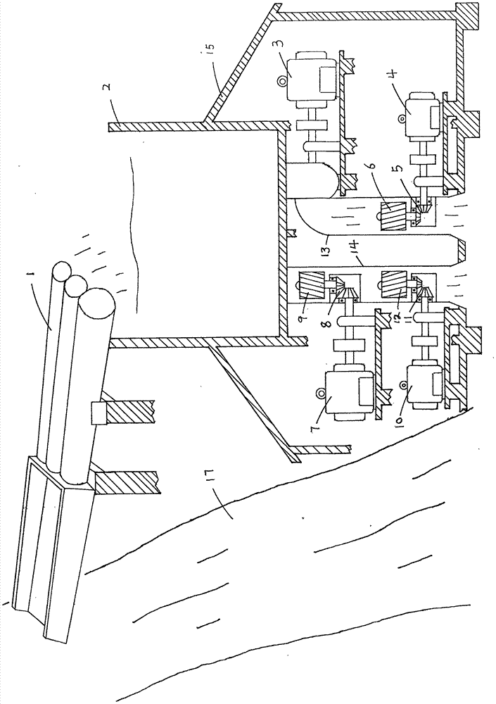
[0015] Water diversion, water tower, vertical, continuous hydroelectric power generation, including canal and water diversion pipe (1), diverting water from river (17) to water tower (2), there is a vertical circular hole power generation channel (13) at the bottom of the water tower in Erfang (15) ), the inside directly installs the mixed-flow hydroelectric generating set (3), and the bottom is the shaft-through water turbine (6), which drives the bevel gear drive (5), drives the shaft-through generating set (4), and realizes the continuous installation of the generating set up and down. A shaft-through water turbine (9) is installed vertically and directly in the round hole power generation channel (14), which drives the bevel gear transmission (8) and drives the generator set (7). (11), drives generator set (10), realizes generator set is installed continuously up and down. The diversion length is 50 meters, the height of the water tower is 5 meters, and the length and widt...

Embodiment 2

[0017] Embodiment 2 is basically the same as Embodiment 1, except that the length of water diversion is 2000 meters, the height of the water tower is 15 meters, and the length and width of the water tower are 15 meters. Larger generator sets and more circular hole power generation channels can be installed.

Embodiment 3

[0019] Embodiment 3 is basically the same as Embodiment 2, except that the length of water diversion is 4000 meters, the height of the water tower is 30 meters, the length and width of the water tower are 30 meters, larger generator sets can be installed, and more circular hole power generation channels can be installed.


PUM

PropertyMeasurementUnit
Length and widthaaaaaaaaaa

Abstract

A water-diversion-type, water-tower-type, vertical-type and continuous-type hydroelectric power generation mode is disclosed. Water is diverted from a river (17) into a water tower through canal jointwater diversion pipes (1), and the water generates the weight pressure at the bottom inside the water tower; a vertical round hole power generation channel (13) is formed in the bottom inside the water tower, a mixed-flow-type water turbine power generation unit (3) is perpendicularly and directly mounted on the bottom face inside the water tower, and an axial-penetrating-type water turbine (6),a bevel gear transmission part (5) and a power generation unit (4) are mounted on the lower portion of the water tower, so that the power generation unit is vertically and continuously mounted; an axial-penetrating-type water turbine (9) is vertically mounted in a round hole power generation channel (14) to drive a bevel gear transmission part (8) and a power generation unit (7); and an axial-penetrating-type water turbine (12) is mounted below the round hole power generation channel (14) to drive a bevel gear transmission part (11) and a power generation unit (10). The water-diversion-type, water-tower-type, vertical-type and continuous-type hydroelectric power generation mode has the advantages that under the same water quantity, the power generation quantity is increased by 30%, investment is reduced by a quarter in comparison, dam injecting and hole digging are avoided, fish migration is not affected, and the hydroelectric power generation mode is novel.

Description

technical field [0001] The invention relates to the field of hydropower generation. Background technique [0002] Electricity is the lifeblood of a country's development, especially clean hydropower. The manufacturing and application of hydropower in my country has reached the advanced level in the world, and the whole industry has shown vigorous development, full of vitality, and economic benefits have increased significantly. However, most of the small and medium-sized hydroelectric power plants are injection dams and digging holes, which are expensive and low in power generation, which affects the migration of fish. Contents of the invention [0003] The purpose of the present invention is to provide a kind of water diversion, water tower, vertical, continuous hydroelectric power generation for the above-mentioned problem, is to lead part of water to the water tower, the height of the water tower, the weight pressure of water, vertical, direct, continuous is used to se...

Claims


Application Information

Patent Timeline
IPC IPC(8): F03B13/00F03B11/00
CPCF03B11/00F03B13/00Y02E10/20
Inventor 王永成
Owner 王永成
Why Eureka
Try Eureka