Engine cooling management system

A technology of engine cooling and management system, which is applied in the direction of engine cooling, engine components, machine/engine, etc. It can solve the problems of inability to effectively control the cooling temperature of various components, achieve effective control of cooling temperature, ensure precise control, and realize precise control Effect

Pending Publication Date: 2018-04-24
DONGFENG COMML VEHICLE CO LTD
View PDF7 Cites 3 Cited by
  • Summary
  • Abstract
  • Description
  • Claims
  • Application Information

AI Technical Summary

Problems solved by technology

[0004] The purpose of the present invention is to overcome the problem that the cooling temperature of each component cannot be effectively controlled in the prior art, and provide an engine cooling management system that can effectively control the cooling temperature of each component

Method used


Image

  • Engine cooling management system

Examples


Embodiment 1

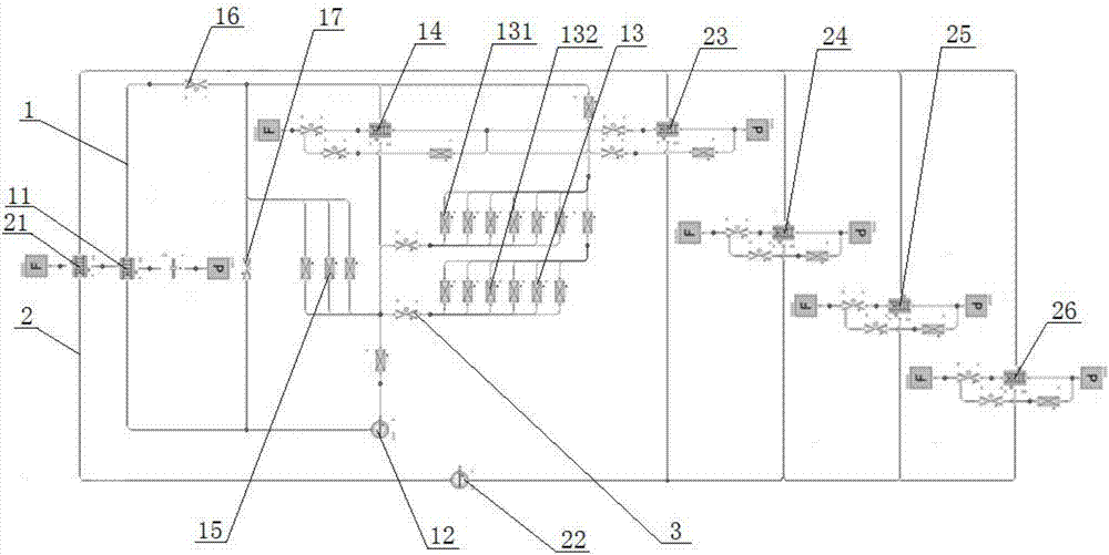
[0032] see figure 1, an engine cooling management system, comprising a high-temperature cooling circulation system 1 and a low-temperature cooling circulation system 2, the high-temperature cooling circulation system 1 comprising a high-temperature cooling water tank 11, a high-temperature cooling water pump 12, an engine body 13, and EGR primary cooler 14, air compressor 15, No. 1 thermostat valve 16, and No. 2 thermostat valve 17. The engine body 13 includes a cylinder block water jacket 131 and a cylinder head water jacket 132 arranged in parallel. The cooling cycle system 2 includes a low-temperature cooling water tank 21, a low-temperature cooling water pump 22, an EGR secondary cooler 23 arranged near the engine intake pipe, a supercharger 24, an oil cooler 25, and an air conditioner 26. Cover water jacket 132, EGR primary cooler 14, and air compressor 15 are arranged in parallel, and the water inlets of cylinder block water jacket 131, cylinder head water jacket 132, EG...


PUM


Abstract

An engine cooling management system comprises a high-temperature cooling circulation system and a low-temperature cooling circulation system. The high-temperature cooling circulation system comprisesa high-temperature heat dissipation water tank, a high-temperature cooling water pump, an engine body, an EGR first-stage cooler and an air compressor. The low-temperature cooling circulation system comprises a low-temperature heat dissipation water tank, a low-temperature cooling water pump, an EGR second-stage cooler, a supercharger, an engine oil cooler and an air conditioner. Through the design, the cooling temperatures of all parts in the cooling system are precisely controlled.

Description

technical field [0001] The invention belongs to the technical field of automobile engine cooling, and in particular relates to an engine cooling management system, which is suitable for realizing precise control of the cooling temperature of each component in the cooling system. Background technique [0002] The cooling system is an important part of the car engine, which has a great influence on the power, economy and reliability of the engine. With the continuous increase of engine speed and power, the requirements for the cooling system are also getting higher and higher. At present, most engines use a closed forced cooling system, mainly including water pumps, thermostats, radiators, machine coolers and other accessories. The cooling path of the coolant is: water pump-machine cooler-engine body-thermostat-radiator - water pump. Since the forced cooling system shares one water pump and water tank, the flow distribution of each accessory depends on piezoresistance, and t...

Claims


Application Information

Patent Timeline
Patent Type & Authority Applications(China)
IPC IPC(8): F01P3/20F01P3/18F01P7/16F02M26/24F02M26/28F02M26/33
CPCF01P3/18F01P3/20F01P7/165F02M26/24F02M26/28F02M26/33F01P2060/12F01P2060/04F01P2050/22F01P2007/146F01P2005/105F01P2003/182
Inventor 周祥军周杨刘喆陈功军
Owner DONGFENG COMML VEHICLE CO LTD
Why Eureka
Try Eureka