
Frame profiled element, wall element, and framework for a clean gas chamber

A technology of clean gas and wall components, applied in the direction of long-strip structural members for load-bearing, wing frame, window/door frame, etc., can solve the problems of large size, complicated installation and heavy weight of the inert gas shell, To achieve the effect of mechanical firmness, high bending rigidity and low weight

Active Publication Date: 2018-04-20
布劳恩惰性气体系统有限公司 +1
View PDF4 Cites 2 Cited by
  • Summary
  • Abstract
  • Description
  • Claims
  • Application Information

AI Technical Summary

Problems solved by technology

[0006] The disadvantage of this inert gas enclosure is its large size and weight, which complicate transport to and installation at the production site

Method used


Image

  • Frame profiled element, wall element, and framework for a clean gas chamber
  • Frame profiled element, wall element, and framework for a clean gas chamber
  • Frame profiled element, wall element, and framework for a clean gas chamber

Examples


Embodiment Construction

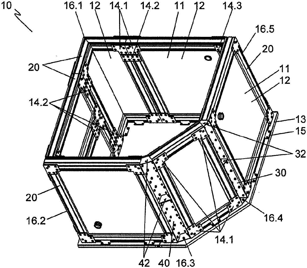
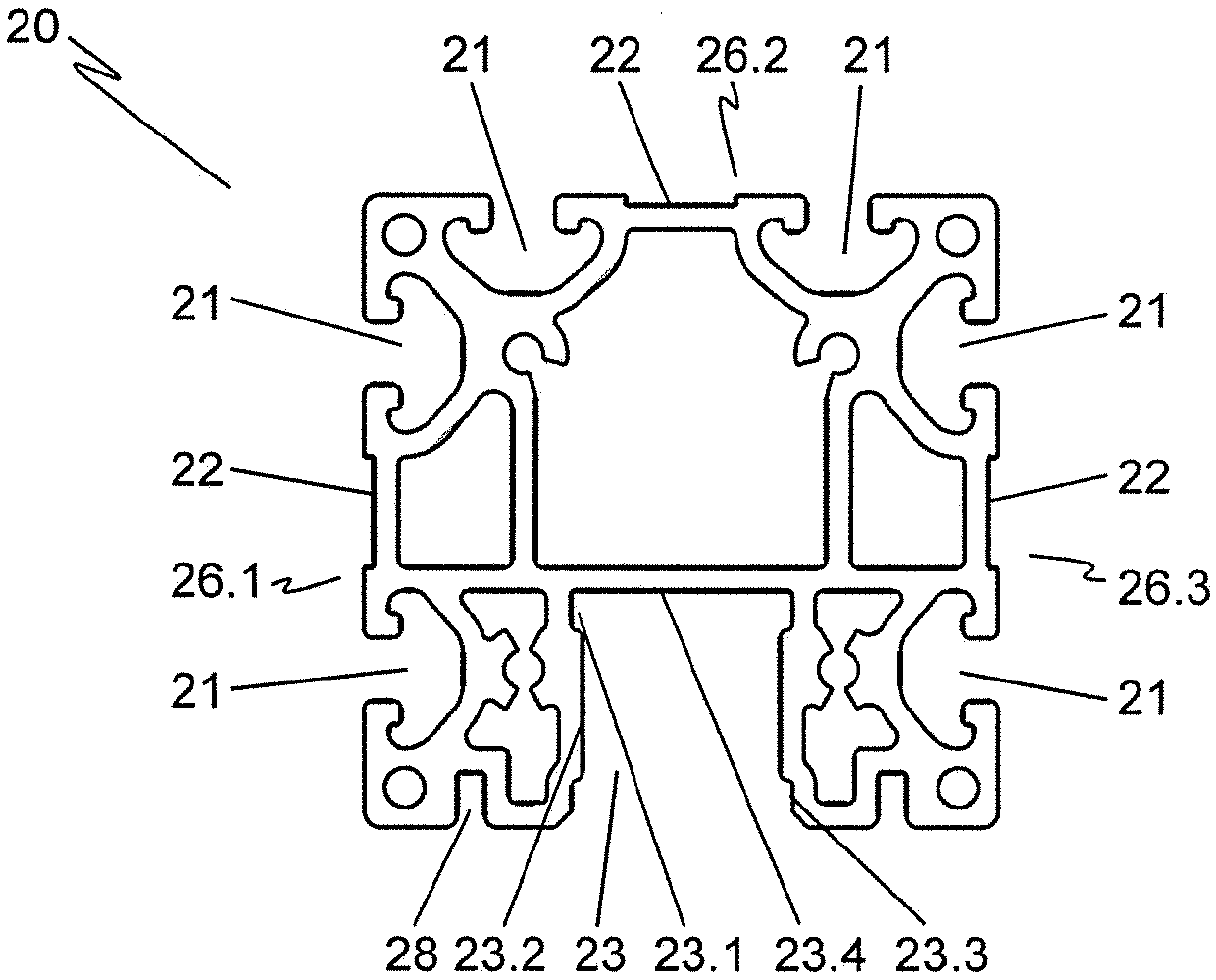
[0037] figure 1 A perspective view of a partially assembled clean gas chamber 10 with a frame made of frame profile A 20 is shown, in image 3 The frame profile A 20 is shown in more detail in .

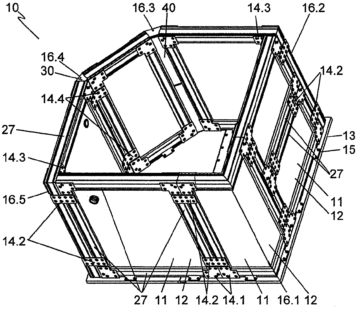
[0038] figure 2 shows the view from the opposite direction with the figure 1 Perspective view of a clean gas chamber assembled in the same part of the frame made of frame profile B 27, in Figure 6 The frame profile B 27 is shown in cross section in .

[0039] figure 1 and figure 2 The clean gas chamber 10 shown has a profile with five corners 16.1, 16.2, 16.3, 16.5 and 16.5. To this end, wall elements 11 in the form of side wall elements are placed along the outer edge of the base 13 and are connected to said base via holding brackets 15 . In the present case of an aluminum honeycomb core, the base 13 is formed by the structural core 12 . The wall element 11 is formed by a plate element surrounded by frame profiles 20 , 27 . In this exemplary embodiment the panel elements...


PUM


Abstract

The invention relates to a frame profiled element, a wall element, and a framework of a clean gas chamber. The structure of the clean gas chamber enables simple assembly of the clean gas chamber at the location of use of the clean gas chamber, wherein the dimensions of the clean gas chamber can be easily adapted to the requirements of the systems to be enclosed.

Description

technical field [0001] The invention relates to frame profiles, wall elements and frames for clean gas chambers formed from frame profiles. Background technique [0002] Many manufacturing processes and procedures in production and R&D cannot be carried out under normal environmental conditions and require separate atmospheres. Such manufacturing processes can be coating operations, e.g. in the manufacture of semiconductors, encapsulation steps in LCD or OLED production or production processes of ultra-pure raw materials, e.g. in medical or pharmaceutical engineering as well as in welding applications (especially titanium welding) . For example, the process may require clean room conditions, low humidity, an inert gas atmosphere, or a combination of different conditions of this type and others. [0003] It is known to carry out such manufacturing processes or procedures in closed spaces where an atmosphere can be established according to the desired conditions. The enclos...

Claims


Application Information

Patent Timeline
Patent Type & Authority Applications(China)
IPC IPC(8): E06B1/36E06B3/08E04C3/04E04B2/74
CPCE06B1/363E04B2002/7498E04C2003/0439E04C2003/0465E06B3/9641
Inventor 格哈德·施普赖策马丁·克普克扬·洛伊波尔德
Owner 布劳恩惰性气体系统有限公司
Learn More