
Blocking stator punching sheet, stator core and motor

A technology of stator punching and stator core, which is applied in the field of motors, can solve the problems of affecting electromagnetic noise and motor efficiency, large fluctuations in motor cogging torque, expensive winding machine equipment, etc., to reduce material costs, work magnetic The effect of small flux leakage and fast winding speed

Inactive Publication Date: 2018-04-20
合肥市通得力电气制造有限公司
View PDF4 Cites 0 Cited by
  • Summary
  • Abstract
  • Description
  • Claims
  • Application Information

AI Technical Summary

Problems solved by technology

[0003] Most of the stator punches on the market now have a circular structure. When processing the stator punch, it is usually formed by punching the entire punching material. After punching, the circular periphery and the stator slot part become waste, which causes raw materials. Waste, resulting in low utilization rate of silicon steel sheet material, which increases manufacturing cost;
[0004] The width of the existing stator punching slot is large, the motor cogging torque fluctuates greatly, and the magnetic flux leakage of the breath part is large, which affects the electromagnetic noise and the efficiency of the motor;
[0005] For ring-shaped punches, the winding machine equipment is expensive and the manufacturing efficiency is low

Method used


Image

  • Blocking stator punching sheet, stator core and motor
  • Blocking stator punching sheet, stator core and motor
  • Blocking stator punching sheet, stator core and motor

Examples


Embodiment 1

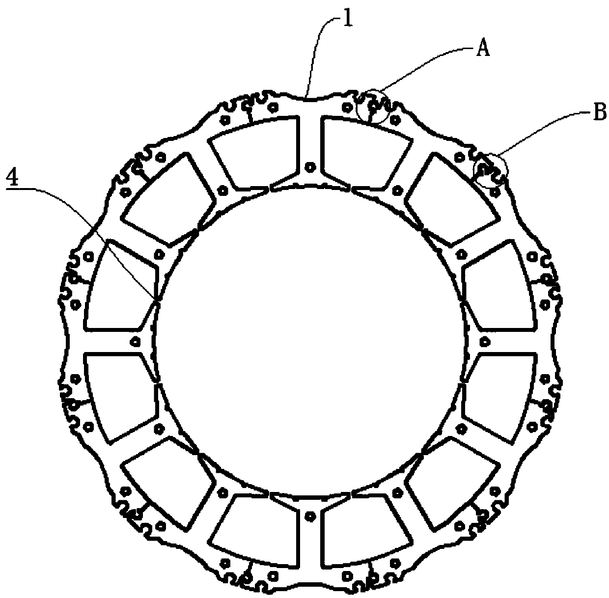
[0038] Such as figure 1 , 5 , 8, a segmented stator punching, including the stator punching body and stator teeth distributed radially on the circumference of the stator punching body, stator slots are formed between adjacent stator teeth, the segmented stator punching Slice 1 is formed by the end-to-end connection of independent tooth-shaped units 2. The bottom of the tooth-shaped unit 2 is provided with a virtual slot 5. The segmented stator punching sheet 1 has low requirements for high punching punches and molds. The iron cores can be double-rowed and arranged side by side. For the plug-in high punching die, the utilization rate of the silicon steel sheet material is high, and the waste material is less, which effectively reduces the material cost. The bottom of the tooth-shaped unit 2 is provided with a dummy groove 5, and the number of the dummy grooves 5 is 2. The structure is to reduce cogging torque, thereby reducing motor noise.

[0039] In the prior art, the slot ...

Embodiment 2

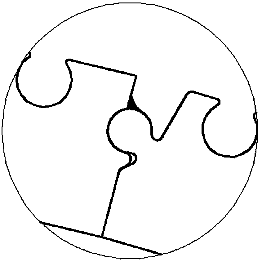
[0045] refer to figure 1 , 5 , 6, the structure of this embodiment is basically the same as that of Embodiment 1, and the similarities will not be repeated. The difference is that: the toothed unit 2 is provided with a rivet 3, and the rivet 3 is located on the horizontal plate 21 The two ends of the vertical plate 22 and the bottom end of the vertical plate 22, this structure is used for punching the self-fastening iron core of the mold, so as to cancel the manual riveting, and the riveting buckle 3 at the same position of the segmented stator punching piece 1 is at the same On a circle, the structure is center-shaped.

Embodiment 3

[0047] refer to figure 1, the structure of this embodiment is basically the same as that of Embodiment 1, and the similarities will not be repeated. The difference is that the width of the notch 4 of the segmented stator punching sheet is 0.8 mm, and the working magnetic flux leakage is small, which effectively reduces the Electromagnetic noise, improving motor efficiency.


PUM


Abstract

The invention relates to the technical field of a motor, in particular to a blocking stator punching sheet, a stator core and a motor. The blocking stator punching sheet is formed by encircling tooth-shaped units independent to each other in an end-to-end way, a virtual groove is formed in the bottom of each tooth-shaped unit, the stator core is formed by laminating a plurality of blocking statorpunching sheets along an axial direction, and a motor comprises the stator core. The blocking stator punching sheet is low in requirement of a high punching machine and a high-punching die, the iron core can employ abutted high-punching dies in dual lines and in parallel, the silicon steel sheet material utilization ratio is high, a few waste is generated, the material cost is effectively reduced,and the blocking stator punching sheet is small in groove opening width; and with a tooth-top virtual groove structure, the working flux leakage is small, the electromagnetic noise is effectively reduced, the motor efficiency is improved, the blocking stator punching sheet is simple in winding and rapid in winding speed, various types of winding machines can be used in industry, and the manufacturing cost is effectively reduced.

Description

Technical field: [0001] The invention relates to the technical field of electric motors, in particular to a segmented stator punch, a stator core and a motor. Background technique: [0002] The motor refers to an electromagnetic device that realizes the conversion or transmission of electric energy according to the law of electromagnetic induction. It consists of a stator and a rotor. The stator includes stator punching and stator windings. [0003] Most of the stator punches on the market now have a circular structure. When processing the stator punch, it is usually formed by punching the entire punching material. After punching, the circular periphery and the stator slot part become waste, which causes raw materials. Waste, resulting in low utilization rate of silicon steel sheet material, which increases manufacturing cost; [0004] The width of the existing stator punching slot is large, the motor cogging torque fluctuates greatly, and the magnetic flux leakage of the b...

Claims


Application Information

Patent Timeline
Patent Type & Authority Applications(China)
IPC IPC(8): H02K1/16H02K1/06H02K5/24
CPCH02K1/165H02K1/06H02K5/24
Inventor 张健王轲王海传
Owner 合肥市通得力电气制造有限公司
Learn More