
A method of robot shaking suppression

A vibration suppression and robot technology, applied in the direction of instruments, adaptive control, general control system, etc., can solve problems such as robot end vibration

Active Publication Date: 2020-08-28
NANJING ESTUN AUTOMATION CO LTD
View PDF7 Cites 0 Cited by
  • Summary
  • Abstract
  • Description
  • Claims
  • Application Information

AI Technical Summary

Problems solved by technology

[0005] The purpose of the present invention is to overcome the defects in the prior art, and propose a robot shake suppression method, based on load trajectory planning and feedforward control, to solve the problem of the end shake of the robot when the action stops

Method used


Image

  • A method of robot shaking suppression
  • A method of robot shaking suppression
  • A method of robot shaking suppression

Examples


Embodiment

[0056] The implementation of the present invention takes a six-joint series industrial robot as an example. Each joint of the robot is controlled separately, and the shaking suppression method of the present invention is used on each joint respectively. In order to simplify the description of the vibration suppression effect, the first joint among the six joints is taken as an example. This robot joint uses a harmonic reducer as the transmission mechanism. The reduction ratio of the reducer is 121, and the stiffness coefficient is 87×10 4 Nm / rad, the damping coefficient is 15Nm / (rad / s).

[0057] Taking a section of the path in the continuous working process of the robot as an example, the path is Figure 4 From A to B in , the action path planning is that the first joint of the robot moves from -14.836° to 7.320° within 0.8s, and the original given joint position, joint velocity, and joint acceleration are as follows: Figure 4 shown.

[0058] Step 1: The output of the con...


PUM


Abstract

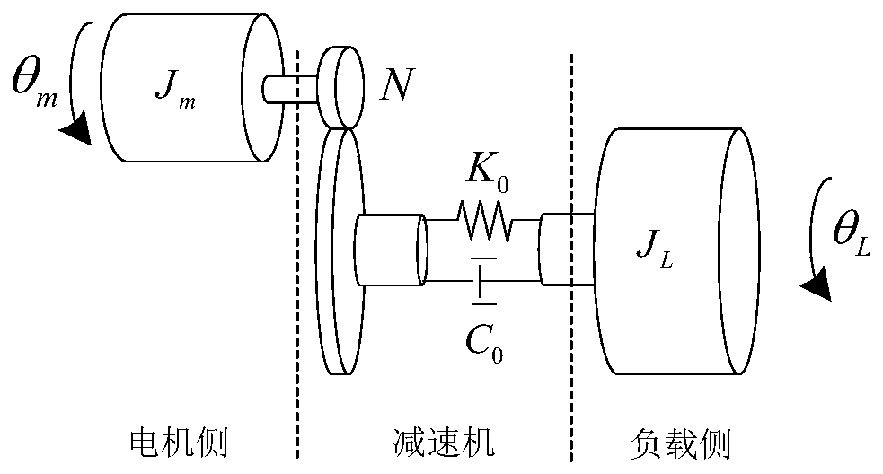
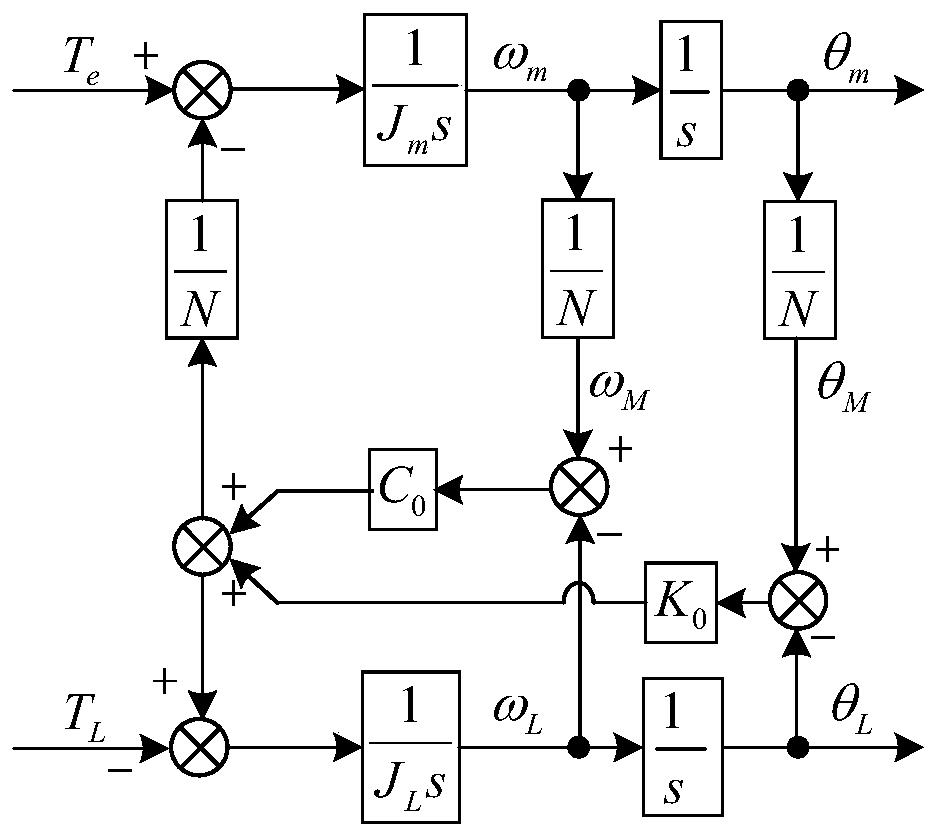
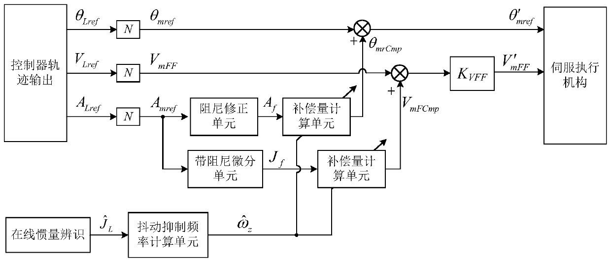
The invention discloses a robot jitter suppression method, which is characterized in that joints of the robot are controlled separately; for each joint, a robot flexible joint part is indirectly replaced with a two-mass system; a corrected position tutoring and feed feedforward of a motor end are solved according to a two-mass system model, the solved corrected position tutoring of the motor end is used as a new position given signal of the motor end, and the solved corrected speed feedforward of the motor end is used as new speed feedforward of the motor end. According to the robot jitter suppression method provided by the invention, starting from the tutoring sent from an upper computer to the motor, using planning of the trajectory of a load end as the objective, and the original planned trajectory of the upper computer is optimized, thereby achieving the purpose of suppressing tail end jitter of the robot. At the same time, to prevent noise influence of second-order differential inan algorithm implementation process, an acceleration signal generated by the upper computer trajectory planning is utilized to realize adjustment of the position tutoring.

Description

technical field [0001] The invention relates to a robot shaking suppression method. Background technique [0002] Due to the existence of flexible links such as reducers, industrial robots are prone to shake at the end or even the entire device during positioning. In trajectory planning, planning a relatively gentle trajectory can improve this phenomenon, but it affects the working efficiency of the robot. The input shaping method is a well-known method to suppress the vibration of the end of the flexible arm, but this method affects the working efficiency of the robot due to the delay processing of the instructions. [0003] Since the position sensor is generally used on the motor side instead of the load side in industrial robots, it is impossible to directly control the load end, resulting in end position deviation and easy to cause end vibration. Therefore, some patents and documents propose to estimate the load position through a certain algorithm, and use the estimat...

Claims


Application Information

Patent Timeline
Patent Type & Authority Patents(China)
IPC IPC(8): G05B13/04
CPCG05B13/042
Inventor 施海红胥小勇杨凯峰徐正华钱巍
Owner NANJING ESTUN AUTOMATION CO LTD
Learn More