
Vertical annealing furnace for bonding wire

A technology of vertical annealing furnace and bonding wire, applied in the direction of furnace, heat treatment furnace, furnace type, etc., can solve the problems of slow cooling speed, high cost, long cooling time, etc., achieve good cooling effect, not easy to oxidize, low cost effect

Active Publication Date: 2018-04-20
NINGBO KANGQIANG ELECTRONICS CO LTD
View PDF10 Cites 6 Cited by
  • Summary
  • Abstract
  • Description
  • Claims
  • Application Information

AI Technical Summary

Problems solved by technology

[0003] However, the existing vertical annealing furnace for bonding wires still has the following technical problems: due to the use of nitrogen for annealing and cooling, and the cooling rate of nitrogen is relatively slow, the cooling time is required to be longer, and there may be bonding wires when nitrogen is used for cooling. The surface is cooled, but the inside is not completely cooled, resulting in an unsatisfactory anti-oxidation effect. In addition, the cost of nitrogen cooling is also high

Method used


Image

  • Vertical annealing furnace for bonding wire
  • Vertical annealing furnace for bonding wire
  • Vertical annealing furnace for bonding wire

Examples


Embodiment

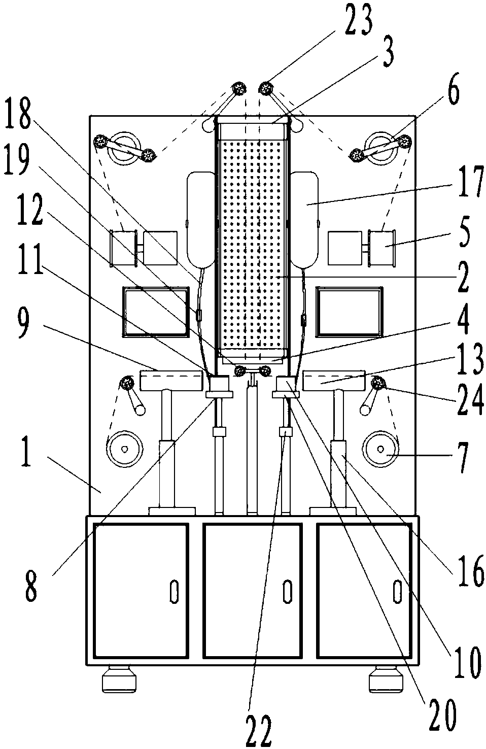
[0027] A vertical annealing furnace for bonding wires, comprising a frame 1 and an annealing assembly arranged on the frame 1, the annealing assembly includes a heating device 2, the heating device 2 is the prior art, for example, a quartz tube is used for heating , the heating device 2 is vertically arranged and the upper end is an inlet end 3, and the lower end is an outlet end 4, and the frame 1 is provided with a pay-off shaft 5 near the wire inlet end 3 of the heating device 2, and the pay-off shaft 5 and the wire-entry end 3 of the heating device 2 is also provided with a tension control assembly 6, and the frame 1 is provided with a take-up shaft 7 close to the wire-out end 4 of the heating device 2, and the annealing assembly also includes a 1 and a liquid cooling device 8 and an air-drying device 9 between the outlet end 4 of the heating device 2 and the take-up shaft 7, the liquid cooling device 8 includes a container 10 with an open upper end arranged on the frame 1 ...


PUM


Abstract

A vertical annealing furnace for a bonding wire comprises a rack and an annealing assembly arranged on the rack. The annealing assembly comprises a heating device. The vertical annealing furnace is characterized in that the part, close to the wire inlet end of the heating device, of the rack is provided with an unwinding shaft, and the part, close to the wire outlet end of the heating device, of the rack is provided with a winding shaft; the annealing assembly further comprises a liquid cooling device and an air drying device, and the liquid cooling device and the air drying device are arranged on the part, located between the wire outlet end of the heating device and the winding shaft, of the rack; the liquid cooling device comprises a container with the upper end opened, the container isarranged on the rack and used for containing annealing liquid with the liquid face higher than the upper end face of the container; and the air drying device is located behind the liquid cooling device, the position close to the wire outlet end of the heating device is further provided with a first guiding device, the first guiding device is used for guiding the direction of the bonding wire discharged out of the wire outlet end position of the heating device into the horizontal direction and making the bonding wire immersed in the annealing liquid above the upper end face of the container. The vertical annealing furnace for the bonding wire is good in cooling effect and anti-oxidization effect and low in cost.

Description

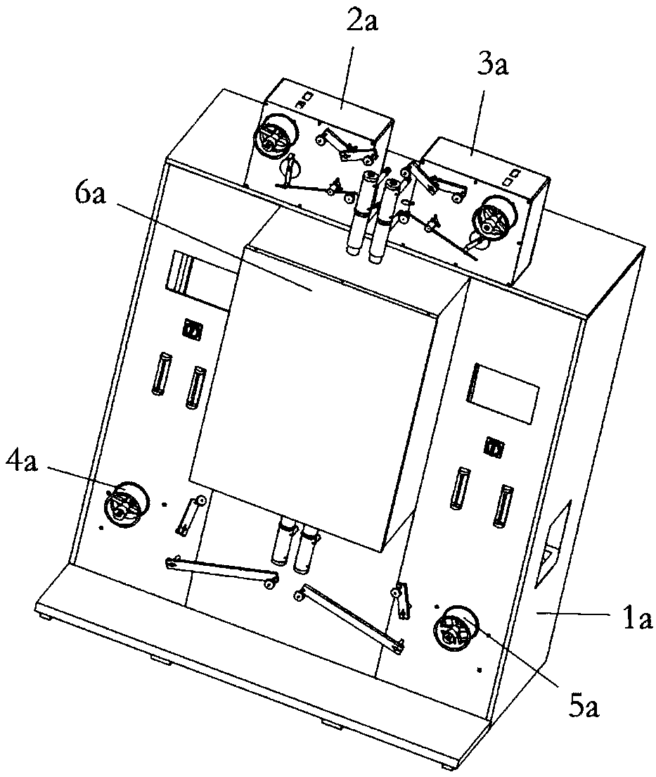
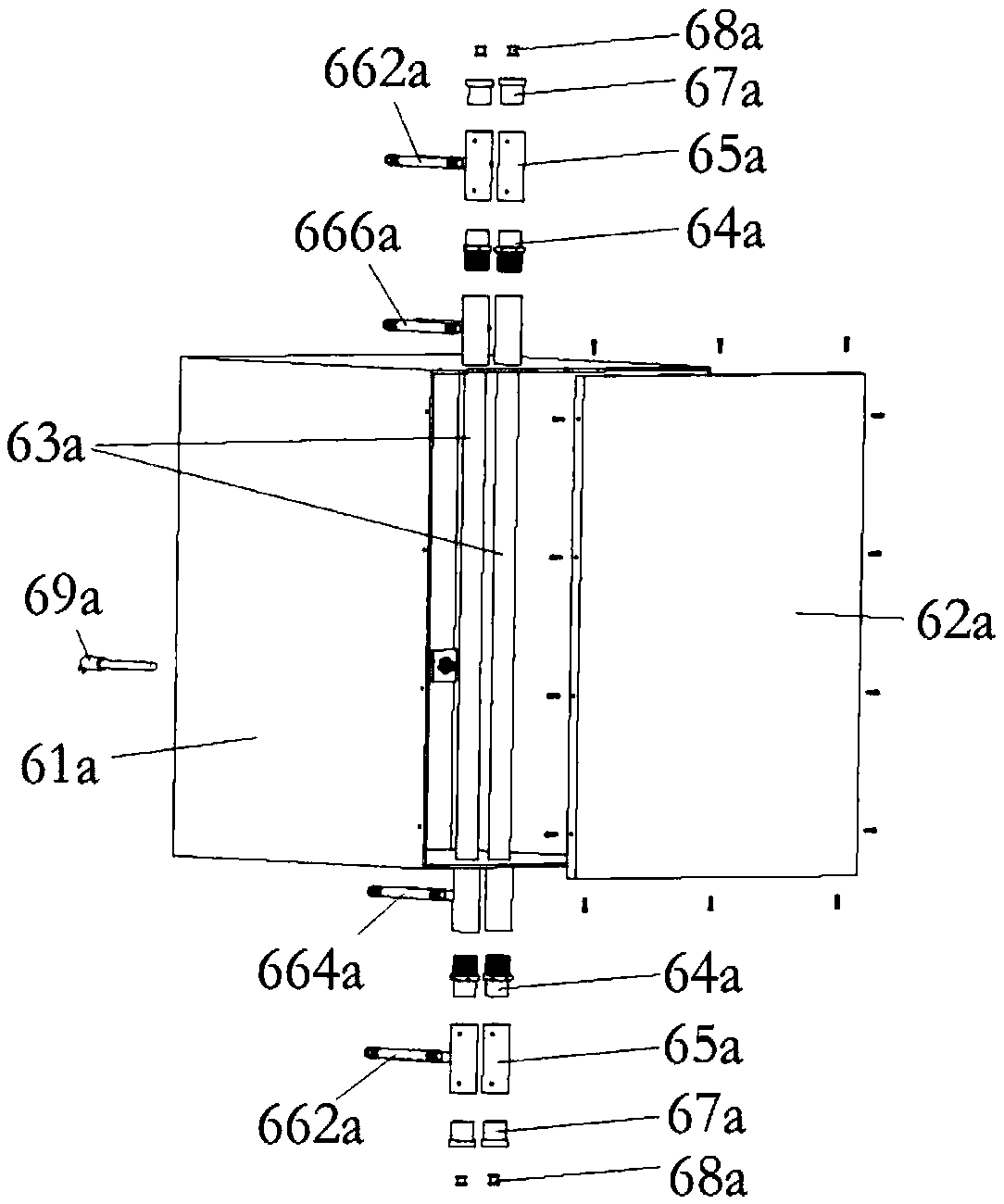
technical field [0001] The invention relates to the technical field of annealing furnaces, in particular to a vertical annealing furnace for bonding wires. Background technique [0002] Annealing is a metal heat treatment process, the metal is first slowly heated to a certain temperature, kept for a sufficient time, and then cooled at an appropriate speed. The purpose is to reduce hardness, improve machinability, eliminate residual stress, stabilize size, reduce deformation and crack tendency, refine grain, adjust structure and eliminate structure defects. The Chinese utility model patent whose authorization announcement number is CN204080036U discloses a kind of vertical annealing furnace, and its structure is as follows: figure 1 As shown, it includes the main body case 1a, the left tension control box 2a, the right tension control box 3a, the left take-up shaft 4a, the right take-up shaft 5a and the annealing assembly 6a; the left tension control box 2a is installed on t...

Claims


Application Information

Patent Timeline
Patent Type & Authority Applications(China)
IPC IPC(8): C21D1/26C21D9/573
CPCC21D1/26C21D9/5732
Inventor 郑磊郑康定郑康良冯小龙杨董斌
Owner NINGBO KANGQIANG ELECTRONICS CO LTD
Learn More