
Dismounting device

A technology for disassembling devices and impact parts, which is applied in the direction of hand-held tools and manufacturing tools, which can solve the problems of inconvenient disassembly, heavy weight, and large dimensions of blind mating components, shorten maintenance and repair time, reduce labor costs, The effect of easy disassembly

Inactive Publication Date: 2018-04-20
BEIJING INST OF RADIO MEASUREMENT
View PDF5 Cites 2 Cited by
  • Summary
  • Abstract
  • Description
  • Claims
  • Application Information

AI Technical Summary

Problems solved by technology

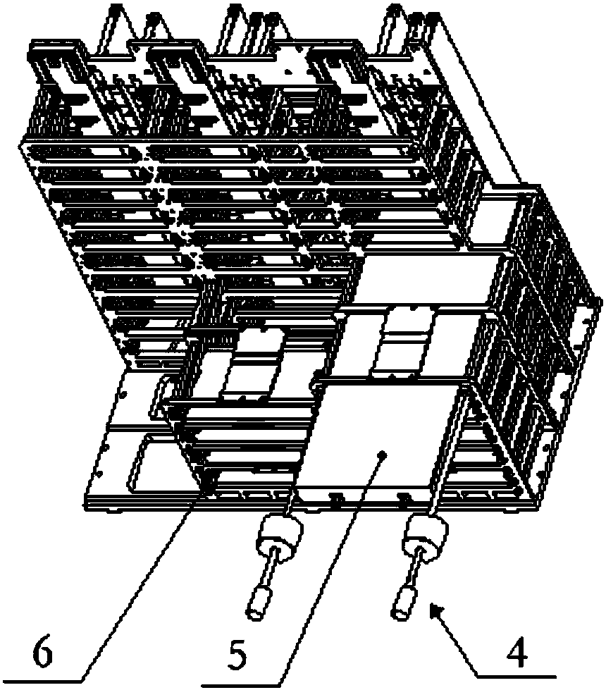
[0004] The embodiment of the present application proposes a disassembly device 4 for blind mating components to solve the problem of inconvenient disassembly of blind mating components with large dimensions and heavy weight on equipment fixed against the wall

Method used


Image

  • Dismounting device
  • Dismounting device
  • Dismounting device

Examples


Embodiment Construction

[0025] In order to make the technical solutions and advantages of the present application clearer, the exemplary embodiments of the present application will be described in further detail below with reference to the accompanying drawings. Obviously, the described embodiments are only a part of the embodiments of the present application, rather than all implementations. Exhaustive list of examples. And if there is no conflict, the embodiments in this description and the features in the embodiments can be combined with each other.

[0026] The core idea of ​​this solution is to use the principle of inertial impact, through the rapid sliding of the impact part 2 and the inertial impact force of the limit part 3, to overcome the static friction of the blind-mate device and the frame 6, or the heavier disassembled device 5 The dislocation friction force caused by the inclination generated when sliding on the long-distance guide rail causes the disassembled device 5 to be detached from...


PUM


Abstract

The embodiment of the invention provides a demounting device. The demounting device comprises a guiding part, an impacting part and a limiting part; the limiting part is fixed together with the limiting end of the guiding part; the impacting part is arranged on the guiding part in a sleeving manner, and can do reciprocating motions along the guiding part; under a using state, the locking end of the guiding part is fixed together with equipment to be demounted, the impacting part is moved to the direction of the locking end of the guiding part, the impacting part is used for increasing the impact force of the limiting part of the impacting part, so as to carry out demounting operation on the equipment to be demounted. According to the technical scheme provided by the invention, through impacting force caused by that the impacting part quickly slides and strikes the limiting part, static friction force caused by the connection of a blind matching component equipment and a machine frame,or relatively large friction force caused by inclination when a relatively heavier component equipment slides on a long distance pathway, are overcome. Therefore, the demounting of the blind matchingcomponent equipment is facilitated, the maintenance and repair time is shortened, and the labor cost is lowered.

Description

Technical field [0001] This application relates to the field of equipment installation, and in particular to a disassembly device for blind plug-in components. Background technique [0002] For equipment that is fixedly installed against the wall, especially on-vehicle or airborne equipment, limited by space size, compact structure, and high degree of integration, the electronic components are installed relatively tightly, and the racks where the components are installed are often close to the equipment compartment. The wall is fixed. The components are installed into the rack from the outside of the rack according to a certain arrangement rule. In order to facilitate maintenance, the electrical connection of the components generally adopts the direct plug-in method to meet the maintenance requirements of the equipment. The front end of the component is equipped with multiple sets of connectors and positioning guide pins, and the component is pushed inward from the outside of th...

Claims


Application Information

Patent Timeline
Patent Type & Authority Applications(China)
IPC IPC(8): B25B27/00
CPCB25B27/00
Inventor 马津芬李欢
Owner BEIJING INST OF RADIO MEASUREMENT
Learn More