Pneumatic circuit for numerically controlled lathe pneumatic door opening and closing

A technology of CNC lathes and pneumatic circuits, which is applied to metal processing machinery parts, maintenance and safety accessories, metal processing equipment, etc. Deformation of the guide rail of the pneumatic door, meeting the door opening and closing time requirements, and the effect of closing the door with small vibration and impact

Pending Publication Date: 2018-04-20
JINAN FIRST MACHINE TOOL GROUP
View PDF0 Cites 3 Cited by
  • Summary
  • Abstract
  • Description
  • Claims
  • Application Information

AI Technical Summary

Problems solved by technology

[0002] Due to the special structural requirements, the pneumatic door of CNC wheel hub car used in the prior art has a structural mass that is too large, for example, the mass will be greater than 200kg. At the same time, the customer requires the opening and closing time of the pneumatic door to be as short as possible, and some technical requirements need to be met within 5S. The inner and pneumatic doors can reach a reciprocating stroke of 900mm, minimizing the auxiliary working time of the equipment
The impact of the short switching time of the pneumatic door and the reduction of the auxiliary working time of the equipment is that the faster running speed causes large vibration, large inertia, and poor cushioning of the machine tool, which affects the accuracy of the machine tool. Damage, increase the maintenance time and cost; sometimes the cylinder pressure is too high to cause deformation of the guide rail of the pneumatic door, affecting the sealing effect of the machine tool, etc.
Conventional pneumatic circuit adjustments cannot achieve a satisfactory damping effect under these conditions
If the intake air volume of the speed control valve is reduced, the cushioning effect is good, but the opening and closing time is too long, which does not meet part of the use requirements; otherwise, the opening and closing time meets the requirements, but the cushioning effect is not good, and the impact of the sliding door is serious. Loose screws cannot guarantee the safety and service life of the cylinder

Method used


Image

  • Pneumatic circuit for numerically controlled lathe pneumatic door opening and closing

Examples


Embodiment Construction

[0011] In order to better understand the present invention, the implementation manner of the present invention will be explained in detail below in conjunction with the accompanying drawings.

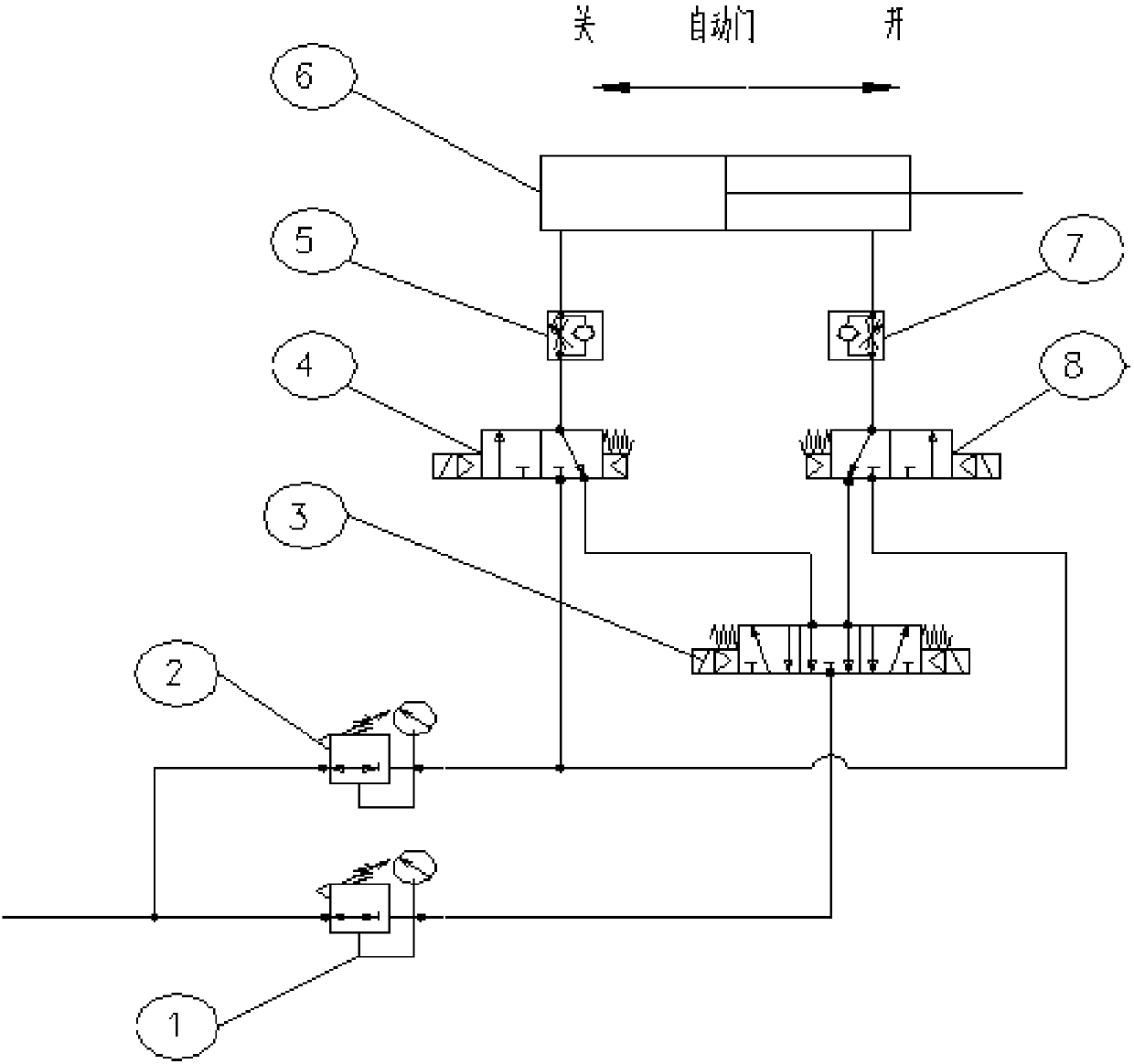
[0012] combine figure 1 , a pneumatic circuit for a pneumatic door switch of a CNC lathe, comprising an exhaust circuit, the exhaust circuit is provided with a high-speed, high-load pneumatic buffer circuit, and the high-speed, high-load pneumatic buffer circuit includes a single-rod double-acting cylinder 6, Pressure reducing valve one 1, pressure reducing valve two 2, speed regulating valve one 5, speed regulating valve two 7, solenoid valve one 4, solenoid valve two 8, solenoid valve three 3, the gas source passes through the pipeline and the pressure reducing valve on the pipeline Pressure valve 1 is connected to the air port on the air source connection side of solenoid valve 3 3, one air port on the cylinder connection side of solenoid valve 3 3 is connected to the air port on the...


PUM


Abstract

The invention discloses a pneumatic circuit for numerically controlled lathe pneumatic door opening and closing. The pneumatic circuit comprises an exhaust loop, and the exhaust loop is provided witha high-speed and high-load pneumatic cushion loop. The high-speed and high-load pneumatic cushion loop comprises a single-pole double-acting pneumatic cylinder, a first reducing valve, a second reducing valve, a first speed regulation valve, a second speed regulation valve, a first electromagnetic valve, a second electromagnetic valve and a third electromagnetic valve. An air source is connected with the third electromagnetic valve through a pipeline and the first reducing valve on the pipeline, the third electromagnetic valve is connected with the first electromagnetic valve and the second electromagnetic valve, the first speed regulation valve is connected with a piston end cavity of the single-pole double-acting pneumatic cylinder, and the first speed regulation valve is connected withthe first electromagnetic valve. The second speed regulation valve is connected with a connecting pole end cavity of the single-pole double-acting pneumatic cylinder, the second speed regulation valveis connected with the second electromagnetic valve, the second reducing valve is connected with the first electromagnetic valve and the second electromagnetic valve, and the first reducing valve andthe second reducing valve are connected with the exhaust loop. The pneumatic circuit is good in cushioning effect, lightens sliding door impact, avoids loosing of the pneumatic cylinder and sliding door guide rail screws and thus guarantees safety and the service life of the pneumatic cylinder.

Description

technical field [0001] The invention relates to the technical field of control equipment for a pneumatic door of a numerical control machine tool, in particular to a pneumatic circuit for a pneumatic door switch of a numerical control lathe. Background technique [0002] Due to the special structural requirements, the pneumatic door of CNC wheel hub car used in the prior art has a structural mass that is too large, for example, the mass will be greater than 200kg. At the same time, the customer requires the opening and closing time of the pneumatic door to be as short as possible, and some technical requirements need to be met within 5S. The inner and pneumatic doors can reach a reciprocating stroke of 900mm, minimizing the auxiliary working time of the equipment. The impact of the short switching time of the pneumatic door and the reduction of the auxiliary working time of the equipment is that the faster running speed causes large vibration, large inertia, and poor cushion...

Claims


Application Information

Patent Timeline
IPC IPC(8): B23Q11/08
CPCB23Q11/0825
Inventor 张伟谢国亮
Owner JINAN FIRST MACHINE TOOL GROUP
Why Eureka
Try Eureka