
Projection welding device and welding method for flying ring of vibration absorber

A welding method and shock absorber technology, applied in welding equipment, resistance welding equipment, metal processing equipment and other directions, can solve the problems of increasing product man-hours, long time spent, electrode protection measures, etc., to improve processing efficiency and save costs. , Welding firm effect

Active Publication Date: 2018-04-20
NANYANG XIJIAN AUTOMOBILE SHOCK ABSORBER
View PDF8 Cites 3 Cited by
  • Summary
  • Abstract
  • Description
  • Claims
  • Application Information

AI Technical Summary

Problems solved by technology

However, this device needs to adjust the electrodes and sliders many times, which takes a long time, increases the working hours of the product, and does not take protective measures for the electrodes, so the electrodes need to be replaced frequently, which reduces production efficiency

Method used


Image

  • Projection welding device and welding method for flying ring of vibration absorber
  • Projection welding device and welding method for flying ring of vibration absorber
  • Projection welding device and welding method for flying ring of vibration absorber

Examples


Embodiment 1

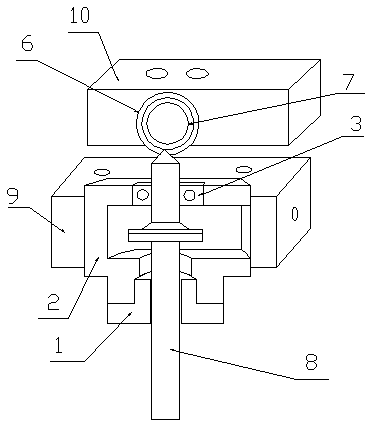
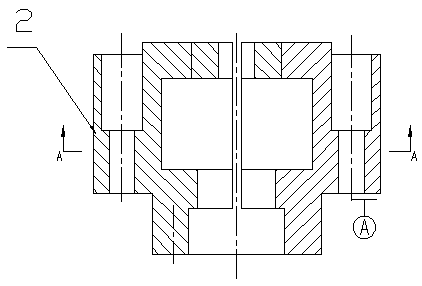
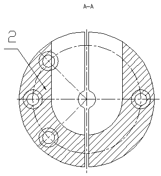
[0039] This embodiment provides a kind of shock absorber suspension ring projection welding device, refer to figure 1 , including a first clamping mechanism and a second clamping mechanism arranged on the projection welding machine; the first clamping mechanism includes an upper electrode block 6, an upper electrode top block 10 arranged on the upper electrode block 6 and The first hydraulic cylinder connected with the upper electrode top block 10, the structure of the upper electrode block 6 refers to Figure 10; The second clamping mechanism includes a lower electrode block 2, a lower electrode top block 9 arranged on the lower electrode block 2 and a second hydraulic cylinder connected with the lower electrode top block 9, the lower electrode The structure of block 2 see figure 2 and image 3 , the upper end of the lower electrode top block 9 is provided with an inlay block 3, and the structure of the inlay block 3 refers to Figure 5 and Figure 6 , the lower end of t...

Embodiment 2

[0045] refer to figure 1 , The projection welding device for suspension rings of the shock absorber provided in this embodiment is an improvement on the basis of Embodiment 1: the material of the clamping block 1 is nylon. The material of the insert 3 is tungsten copper. Tungsten copper has good electrical and thermal conductivity, high hardness, wear resistance, and easy processing. The chrome copper used in the upper electrode block 6 and the lower electrode block 2 has good electrical and thermal conductivity and is wear-resistant.

Embodiment 3

[0047] The shock absorber ring projection welding device provided in this embodiment is an improvement on the basis of the second embodiment: a position sensor is arranged in front of the top block of the upper electrode. A screw is arranged on one side of the lower electrode top block.

[0048] Adjust the opening and tightening of the top block through the two position sensors in front of the top block of the upper electrode, and adjust the screw so that the convex point is in the middle of the lifting ring, so as to prevent the loosening of the lifting ring and cause the unqualified symmetry of the replacement after projection welding, which will cause the workpiece to be scrapped .


PUM


Abstract

The invention provides a projection welding device and a welding method for a flying ring of a vibration absorber and belongs to the technical field of automotive parts assembly. The projection welding device comprises a first clamping mechanism and a second clamping mechanism arranged on a projection welder, wherein the first clamping mechanism comprises an upper electrode block, an upper electrode ejector block arranged on the upper electrode block and a first hydraulic cylinder connected to the upper electrode ejector block; the second clamping mechanism comprises a lower electrode block, alower electrode ejector block arranged on the lower electrode block and a second hydraulic cylinder connected to the lower electrode ejector block; an insert is arranged at the upper end of the lowerelectrode ejector block; a tight holding block is arranged at the lower end of the lower electrode ejector block; and a first button for controlling the first hydraulic cylinder and a second button for controlling the second hydraulic cylinder arranged on the projection welder. The projection welding device provided by the invention can protect electrodes, all parts are quickly and precisely aligned during welding, the labor intensity and the cost can be reduced effectively, and an effect of improving the production efficiency is achieved.

Description

technical field [0001] The invention relates to the technical field of assembly of automobile parts, in particular to a projection welding device and a welding method for suspension rings of shock absorbers. Background technique [0002] The piston rod assembly is one of the important components of the shock absorber, generally including the piston rod, lifting ring, dust cover and so on. These parts are basically combined with the piston rod by welding. The dust cover and the piston rod belong to an interference fit, and are welded after press-fitting; the lifting ring and the piston rod are welded by projection welding. Since the lower electrode needs to hold the piston rod tightly during projection welding, the lower electrode is easy to wear, and the lower electrode needs to be replaced frequently Waste a lot of human and material resources. If the lower electrode is not checked and replaced frequently, it will lead to weak welding and unattractive appearance, which wi...

Claims


Application Information

Patent Timeline
Patent Type & Authority Applications(China)
IPC IPC(8): B23K11/14
CPCB23K11/14Y02P70/10
Inventor 何景华王鹏
Owner NANYANG XIJIAN AUTOMOBILE SHOCK ABSORBER
Learn More