Rotary cutter for lawn mower and portable lawn mower using same
A technology of rotary cutters and lawnmowers, which is applied in the fields of weed elimination equipment, applications, animal husbandry, etc., and can solve the problems of preventing the disc-shaped guide part 112 from being stationary, threatening the personal safety of operators, and unable to deny the mowing operation, etc. , to achieve the effect of improving friction and static state, improving safety and reducing clothing scratches
- Summary
- Abstract
- Description
- Claims
- Application Information
AI Technical Summary
Problems solved by technology
Method used
Image
Examples
Embodiment 1
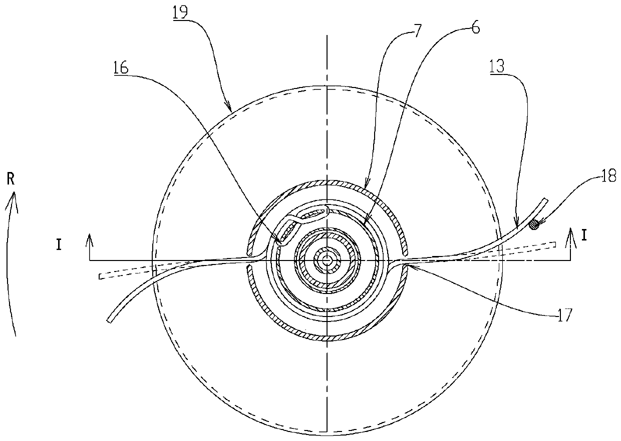
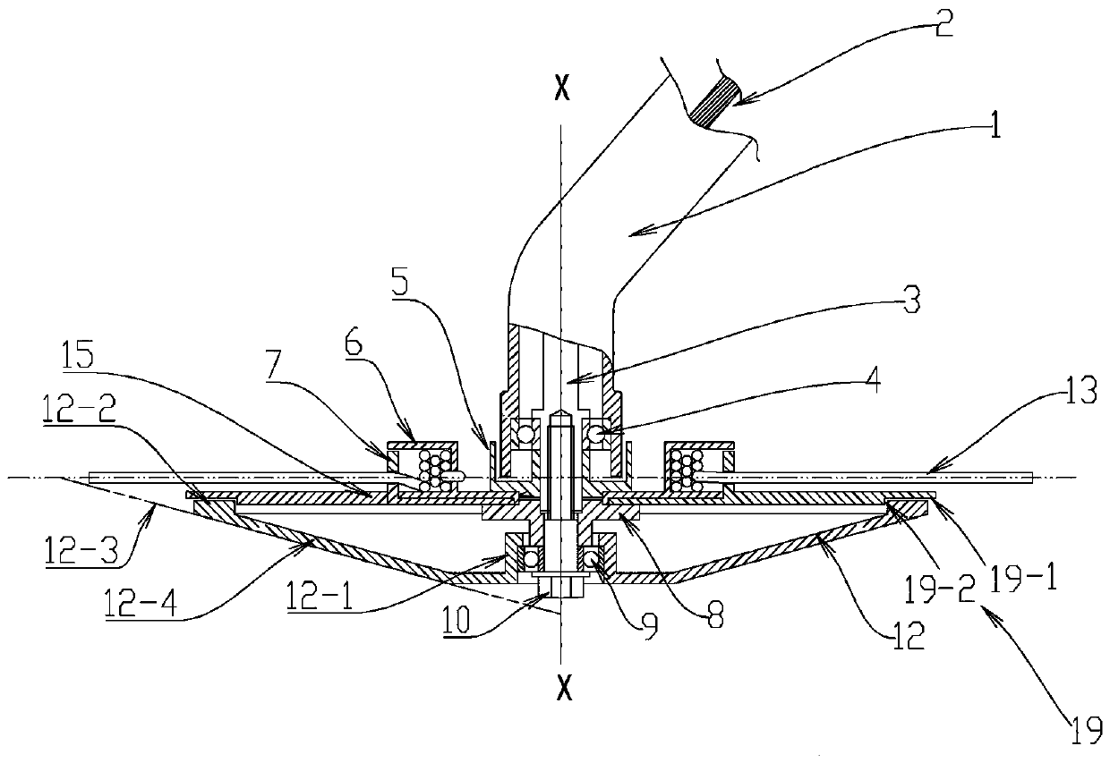
[0056] Embodiment 1: A rotary cutter for a lawn mower, at least including a cutting cutter installation shaft 3, a cutting cutter 13 rotating around its central axis X-X is installed on the cutting cutter installation shaft 3, and the bottom of the cutting cutter 13 is installed There is a guide member 12 that rotates relative to the cutting tool installation shaft 3 through the center part A12-1, the center part A12-1 is connected with the edge part A12-2 of the guide member through the rotation surface A12-4, and the outer surface of the rotation surface A12-4 is The ridge line A12-3 is formed by rotating around the central axis X-X of the cutting tool installation shaft 3, and the ridge line A12-3 is located outside the parts that rotate around the cutting tool installation shaft 3 except the cutting tool 13. Between the cutting tool 13 and the guide member 12, there is a disc portion A15 that rotates with the cutting tool installation shaft 3, and the notch 19 of the disc p...
Embodiment 2
[0057] Embodiment 2: A rotary cutter for a lawnmower, including a cutting cutter installation shaft 3, on which a cutting cutter reel B24 rotating around its central axis X-X is installed on the cutting cutter installation shaft 3, and the cutting cutter reel B24 is wound And keep the cutting tool 13, the cutting tool holding part 20 with the same central axis X-X as the cutting tool reel B24 is covered on the periphery of the cutting tool reel B24, and the cutting tool holding part 20 rotates together with the cutting tool installation shaft 3; A guide member 12 that rotates relatively around the cutting tool installation shaft 3 is installed below the cutter holding member 20, and a disc portion B45 that rotates with the cutting tool installation shaft 3 is provided between the cutting tool 13 and the guide member 12; The holding member 20 is provided with a cutter extension hole 28 from which the cutting cutter 13 can be extracted. Cover body portion 72, and the outer diame...
Embodiment 3
[0058] Embodiment 3: A rotary cutter for a lawnmower, the guide member 12 includes a central part B41 that rotates around the central axis X-X of the cutting tool installation shaft 3, an edge part B42 of the guide member, and the center part B41 passes through the edge part B42 of the guide member The rotation surface B44 is connected, and the rotation surface B44 is formed by the ridge line A12-3 rotating around the central axis X-X, and the ridge line 12-3 is located outside the parts that rotate around the cutting tool installation axis 3 except the cutting tool 13. The cutting blade holding member 20 further includes an upper cover 22 in which a holding unit body 23 , a cutting blade reel B24 around which the cutting blade 13 is wound and held, and a cylindrical protrusion protruding from the cutting blade reel B24 are assembled. part 54, a pressing spring 26 is installed between the upper cover 22 and the cutting tool reel B24; Cutting tool installation shaft 3 has a loc...
PUM
 Abstract
Description
Claims
Application Information
 - R&D Engineer
- R&D Manager
- IP Professional
- Industry Leading Data Capabilities
- Powerful AI technology
- Patent DNA Extraction
Browse by: Latest US Patents, China's latest patents, Technical Efficacy Thesaurus, Application Domain, Technology Topic, Popular Technical Reports.
© 2024 PatSnap. All rights reserved.Legal|Privacy policy|Modern Slavery Act Transparency Statement|Sitemap|About US| Contact US: help@patsnap.com


