
Sinus and nasal stent

A sinus and nasal technology, applied in stents, nose implants, pharmaceutical formulations, etc., can solve the problems of sinus tissue irritation, patient inconvenience and cost, difficulty in providing compression size, expansion size and expansion force, etc.

Inactive Publication Date: 2018-04-17
MEDTRONIC INC
View PDF9 Cites 7 Cited by
  • Summary
  • Abstract
  • Description
  • Claims
  • Application Information

AI Technical Summary

Problems solved by technology

However, when such scaffolds degrade, they can break into small pieces and produce acidic degradation by-products that can cause irritation to sinus tissue
If the stent needs to be removed due to complications such as advanced inflammation or headaches, this degradation can make it difficult to remove the stent cleanly
The removal may also require the patient to undergo the inconvenience and expense of a follow-up visit
[0005] For some sinus and nasal stent designs, it may also be difficult to provide the proper balance of compressed size, expanded size, and expansion force, especially when the stent must also provide drug-eluting or biodegradable characteristics

Method used


Image

  • Sinus and nasal stent
  • Sinus and nasal stent
  • Sinus and nasal stent

Examples


example 1

[0078] Base support construction

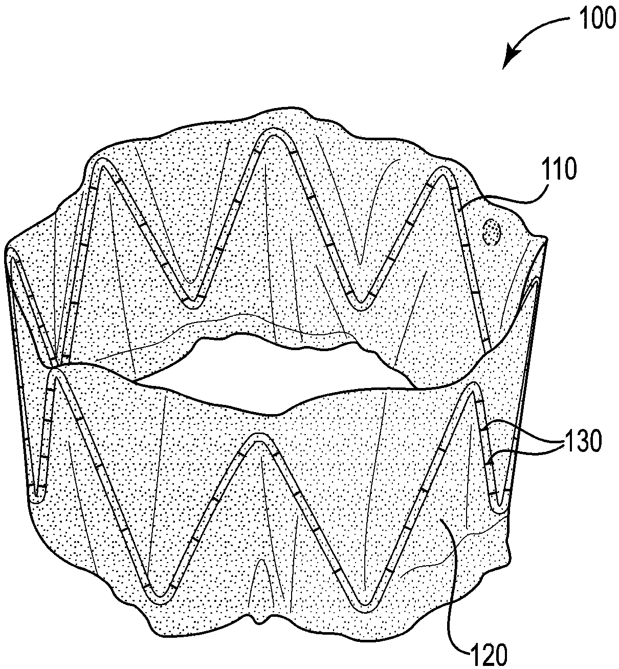
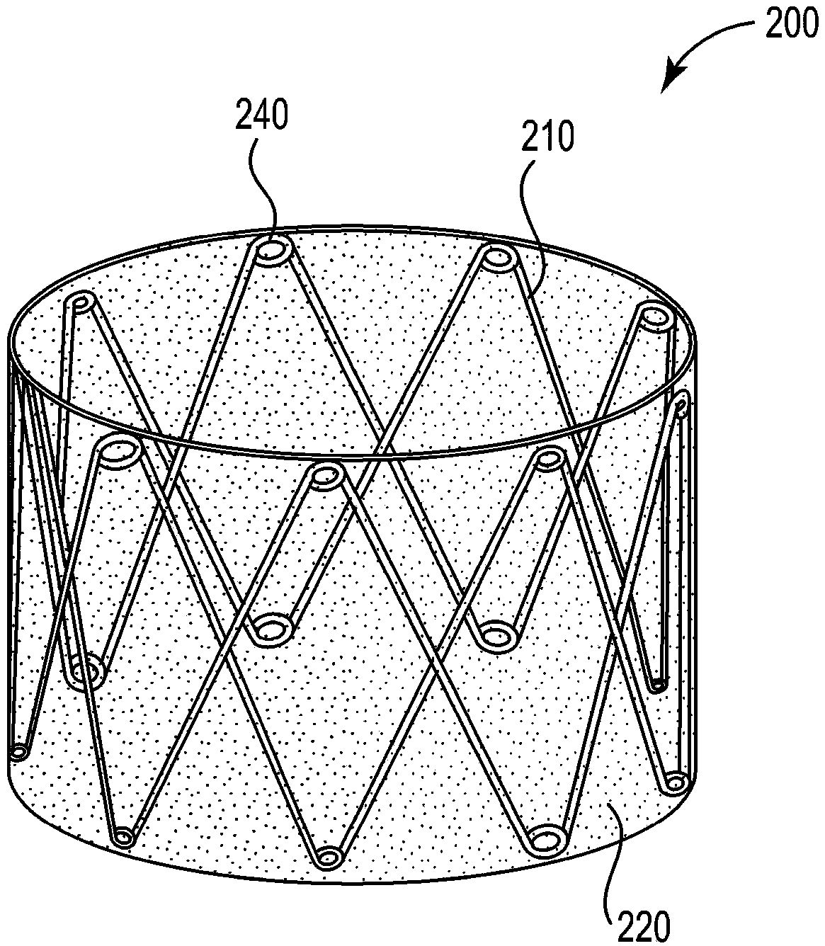
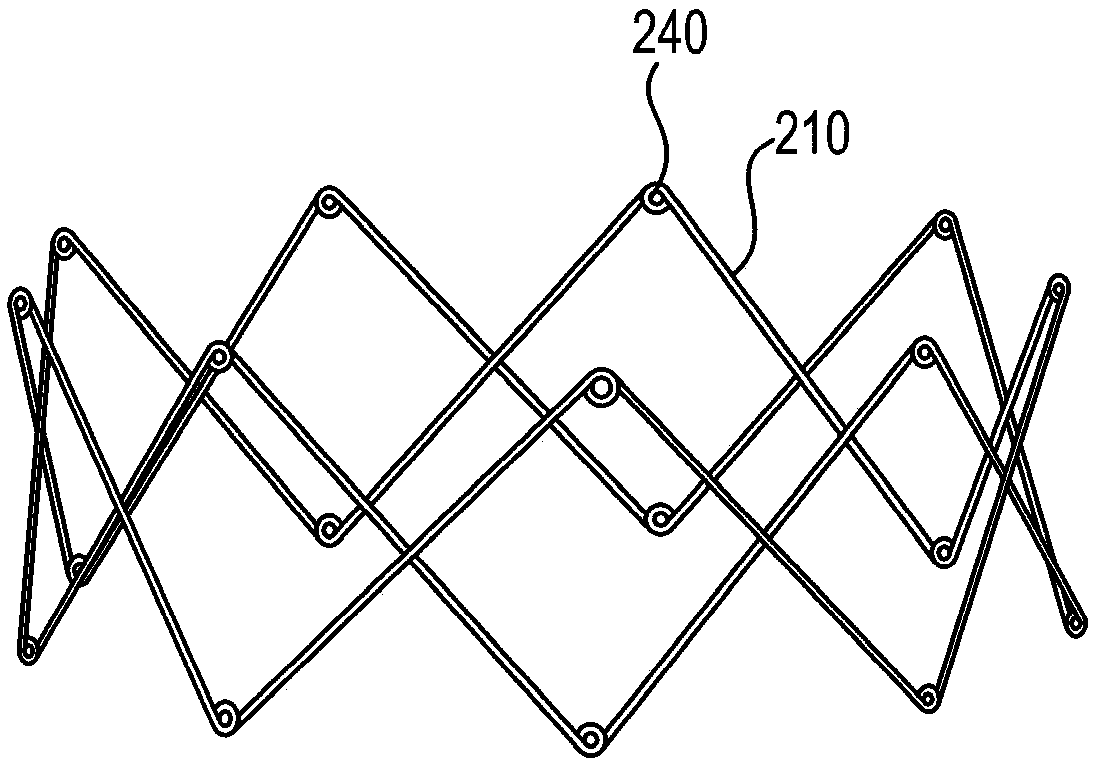
[0079] Hand-fabricated from a length of 0.38 mm diameter 300 series hard stainless steel medical wire (Malin Co., Cleveland, Ohio) with figure 1 The base bracket 110 is similar to the base bracket. Use UNITEK TM A model 101 welder (3M Unitek, Monrovia, CA) welded the ends of the wires together. The completed base scaffold has a diameter of approximately 3 cm, a strut angle of 32°, a strut length of 2 cm, and 7 peaks and 7 valleys.

example 2

[0081] Polyethylene Sleeve Attachment

[0082] Formed similar to the figure 1 The cannulated stent of the stent 100 in the stent has a layer of LOCTITE on the inner surface of the polyethylene film TM 3972 Light Curing Adhesive (Henkel Corp., Rocky Mount, Conn.). The base scaffold was radially compressed sufficiently to reduce its circumference to approximately 7 cm such that the polyethylene film ends overlapped by approximately 1 cm. Use DYMAX TM BLUEWAVE TM A 200 UV curing spotlight (Dymax Corp., Torrington, Conn.) cured the adhesive under 10 seconds of UV light exposure.

example 3

[0084] coating formulation

[0085] Preparation 1. Using PEVA beads (Sigma-Aldrich Co., St Louis, MO) containing 40% by weight vinyl acetate and having a melt index of 8 g / 10 min at 190 °C / 2.16 kg, (PEVA) was dissolved in 20 ml of tetrahydrofuran (THF) (Sigma-Aldrich Co.) to prepare a 5% (w / v) PEVA solution. An 8 mg portion of triamcinolone acetonide (TA) (Sigma-Aldrich Co.) was added and dissolved in the solution.

[0086] Preparation 2. Using PEVA beads having a molecular weight of 337,000 as measured by gel permeation chromatography (Sigma-Aldrich Co.) and poly(butyl methacrylate) (PBMA) powder, by dissolving 1 g of PEVA and 0.5 g of PBMA in 20 ml of THF A solution containing 5% (w / v) PEVA and 2.5% (w / v) PBMA was prepared. 8 mg of TA was partially added and dissolved in the solution.


PUM


Abstract

A stent (100) that is sleeved and radially expandable, and which in an expanded state provides a breathable, generally tubular structure sized and shaped for residence in a sinus or nasal cavity or passage, and in an unexpanded state has a cross-sectional diameter suitable for insertion into such cavity or passage. The sleeve limits expansion and outward pressure exerted by the stent and thereby can prevent or reduce the incidence of headache in patients, and can provide increased surface area for improved elution of drugs to nearby mucosal tissue.

Description

[0001] Cross References to Related Applications [0002] This application claims the benefit of US Provisional Application Serial No. 62 / 210,267, entitled "SINUS AND NASAL STENT," filed August 26, 2015, the disclosure of which is incorporated herein by reference. technical field [0003] The present invention relates to the use of implantable stents to treat sinus and nasal conditions. Background technique [0004] Sinusitis is a disease characterized by inflammation of the mucous lining of the sinuses. Current therapies include corticosteroid therapy to reduce inflammation, and surgery to remove inflamed tissue. After surgery, steroid therapy may be needed to reduce postoperative inflammation. Traditional oral steroids are usually ineffective. Penetration of these systemically delivered agents into the sinus mucosa may be limited due to poor blood flow to the sinuses. Topical applications such as sprays, creams, or gels may also be ineffective due to the steroid not bei...

Claims


Application Information

Patent Timeline
Patent Type & Authority Applications(China)
IPC IPC(8): A61F2/18A61B17/24A61F2/90A61F2/966
CPCA61F2/90A61F2/966A61B17/24A61F2/186A61F2250/0039A61F2/04A61F2/844A61L31/148A61L31/04A61L31/16A61K47/6957A61F2002/072A61F2250/0067A61F2002/075A61F2/07
Inventor 文杰D·A·奥利弗
Owner MEDTRONIC INC
Learn More