Range hood oil discharge structure and range hood

An oil discharge structure and a technology for range hoods, which are used in the removal of oil fume, household stoves/stoves, heating methods, etc., can solve the problems of flowing to the lower end of the mesh plate, entering the housing of the range hood, secondary pollution, etc., and prolonging the working life. , Improve the service life, the effect of large kinetic energy

Active Publication Date: 2019-08-30
QINGDAO HAIER SMART TECH R & D CO LTD +1
View PDF5 Cites 0 Cited by
  • Summary
  • Abstract
  • Description
  • Claims
  • Application Information

AI Technical Summary

Problems solved by technology

The grid disk can intercept oil droplets. Theoretically, under the action of centrifugal force, the oil droplets intercepted by the grid disk will be thrown into the oil collection ring located on the outer peripheral side of the grid disk under the action of centrifugal force. However, when the machine is shut down or the impeller running speed changes suddenly At this time, the oil intercepted on the grid plate will spread out in an irregular track along the edge of the grid plate or flow into the impeller along the intermediate shaft, or flow to the lower end of the grid plate under the action of gravity, and enter the range hood shell, resulting in secondary Pollution

Method used


Image

  • Range hood oil discharge structure and range hood
  • Range hood oil discharge structure and range hood
  • Range hood oil discharge structure and range hood

Examples


Embodiment 1

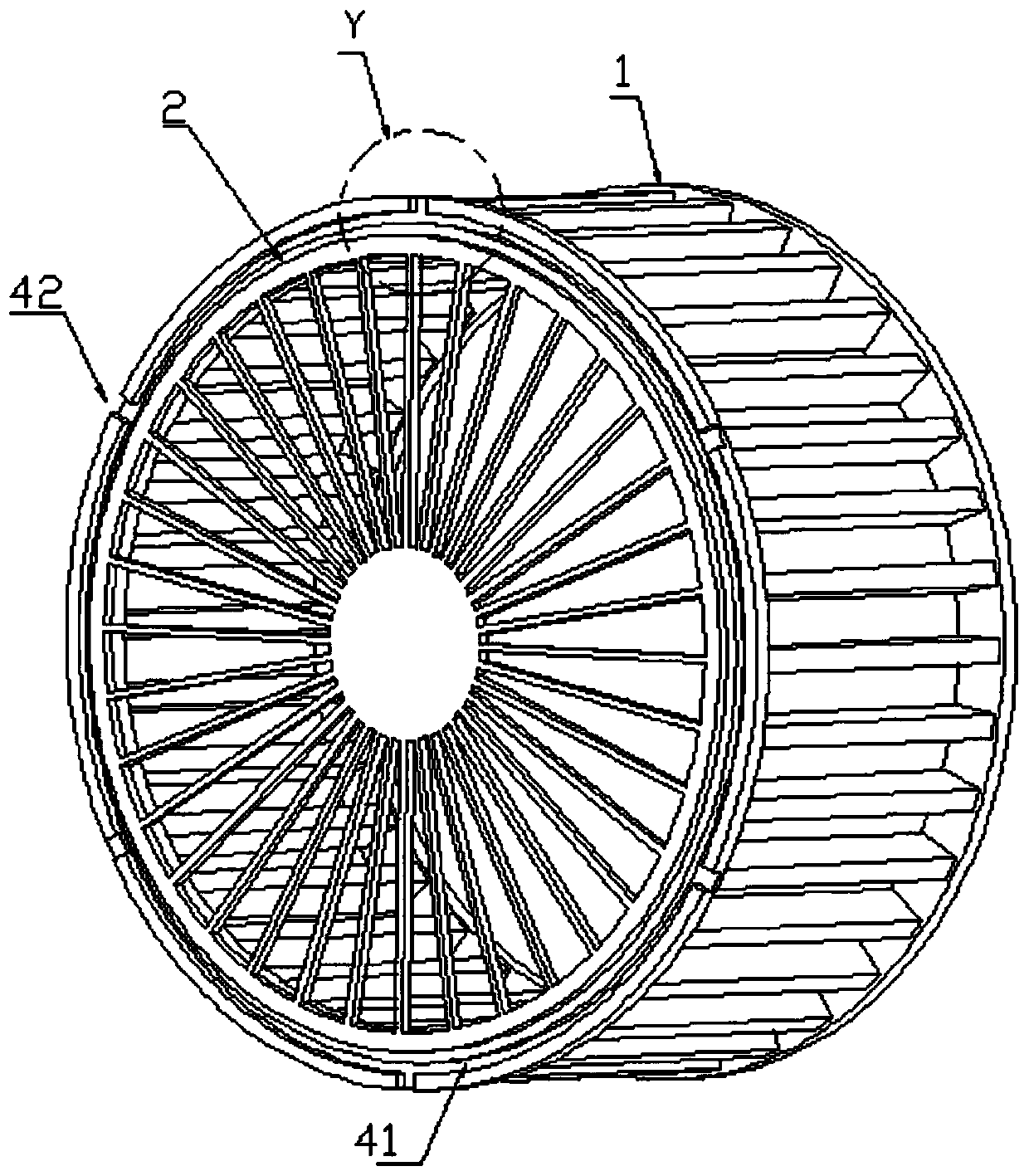
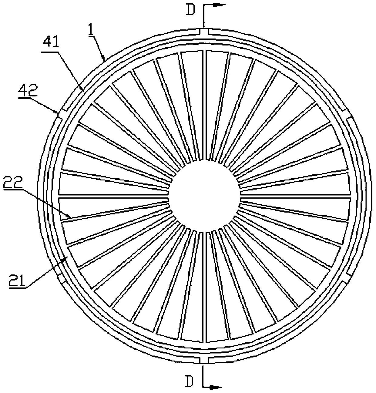
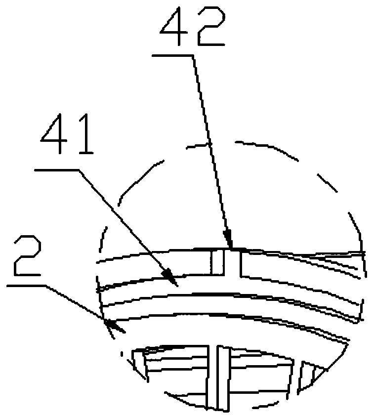
[0039] like Figure 1-4 As shown, in order to facilitate the discharge of the oil droplets intercepted on the mesh disk 2 in a relatively regular manner, the technical solution adopted in this embodiment is that an oil guide structure 4 is provided on the impeller 1, specifically, the mesh disk 2 The periphery is fixedly connected to the front end of the impeller 1, and the oil guide structure 4 includes an oil guide groove 41 and a plurality of oil discharge ports 42 arranged on the side of the oil guide groove 41 away from the axis of the mesh disk 2 for discharging the oil in the oil guide groove 41, The oil discharge ports 42 are evenly distributed along the circumference of the grid plate 2 . The oil guide groove 41 is an annular groove arranged on the front end surface of the impeller 1 , the annular groove surrounds the grid plate 2 , and the oil discharge port 42 extends from one side of the annular groove to the outer peripheral surface of the impeller 1 .

[0040] T...

Embodiment 2

[0047] like Figure 5-6As shown, the difference between this embodiment and Embodiment 1 is that the oil discharge port 42 is an oblique outlet, specifically, the oil discharge port 42 is formed at a certain angle from the bottom surface of the oil guide groove 41 along the direction away from the axis of the mesh disk 2. Inclined through the side wall of the oil guide groove 41,

Embodiment 3

[0049] like Figure 7-8 As shown, in order to discharge the oil droplets intercepted on the network disk 2 in a relatively regular manner, the technical solution adopted in this embodiment is that an oil guide structure 4 is also provided on the network disk 2, and the oil guide structure 4 is arranged along the The radial distribution of the mesh disk 2 is on the periphery of the mesh wire 22, and the oil guide structure 4 includes an oil guide groove 41 and a plurality of holes arranged on the side of the oil guide groove 41 away from the axis of the mesh disk 2 for discharging the oil in the oil guide groove 41. There are four oil discharge ports 42, and the oil discharge ports 42 are evenly distributed along the circumferential direction of the grid plate 2.

[0050] Specifically, the oil guide groove 41 is an annular groove arranged on the outer edge of the grid plate 2 and recessed toward the impeller 1 along the axial direction of the grid plate 2, and the oil discharge...


PUM


Abstract

The invention relates to an oil discharging structure of a range hood. The oil discharging structure comprises an impeller and a net disc arranged on the front side of the impeller. The net disc comprises a framework coaxially arranged with the impeller, and net wires arranged on the framework and used for intercepting oil drops. A circle of oil conduction structure surrounding the net wires is arranged at the front end of the impeller. The oil conduction structure comprises an oil conduction groove and oil discharging openings communicating with the oil conduction groove and used for discharging oil in the oil conduction groove. The invention further relates to a range hood provided with the above oil discharging structure of the range hood. By means of the oil discharging structure of the range hood and the range hood, the oil conduction groove is arranged so that oil drops in the net wires can be collected, and the oil drops are prevented from flowing towards the center of the net disc; and in addition, due to the gathering effect of the oil conduction groove, the mass of the oil drops discharged from the oil discharging openings is large, the oil drops can fly along the straight line more easily and fall into a set oil collecting device, and the problem that small oil drops are thrown out and then are scattered in the impeller due to the wind effect can be avoided.

Description

technical field [0001] The invention relates to the field of kitchen appliances, in particular to an oil discharge structure of a range hood and the range hood. Background technique [0002] The range hood is one of the commonly used kitchen appliances. Its function is to "suck away" the smoke generated by cooking during cooking, also known as smoke separation, so as to reduce the spread of smoke in the indoor air and external emissions. When cooking produces a large amount of oil droplets splashing to the suction port of the range hood, the ideal state is that the range hood can suck these oil droplets into the range hood and separate the oil droplets and collect them in the oil tank. When the oil accumulates to a certain amount, The user pours out the waste oil, and so on. The actual range hood products, due to the current functional limitations, most of them suck oil droplets into the fan, and the oil droplets will stick to the inside of the fan or the impeller, which fi...

Claims


Application Information

Patent Timeline
Patent Type & Authority Patents(China)
IPC IPC(8): F24C15/20
Inventor 闫赛娜许升蔡玉标孟永哲
Owner QINGDAO HAIER SMART TECH R & D CO LTD
Why Eureka
Try Eureka