supercharger

A supercharger and supercharger main body technology, applied in the direction of machines/engines, bearings, shafts, etc., to achieve the effect of improving oil discharge

Active Publication Date: 2016-08-17
IHI CORP
View PDF6 Cites 0 Cited by
  • Summary
  • Abstract
  • Description
  • Claims
  • Application Information

AI Technical Summary

Problems solved by technology

In such a case, there is a possibility that part of the lubricating oil flowing into the insertion hole may be guided to the impeller side instead of flowing into the through hole.

Method used


Image

  • supercharger
  • supercharger
  • supercharger

Examples


Embodiment Construction

[0018] Embodiments of the present invention will be described in detail below with reference to the drawings. Dimensions, materials, other specific numerical values, and the like shown in the present embodiment are merely examples for facilitating understanding of the invention. That is, they do not limit the present invention unless otherwise specified. In this specification and the drawings, elements having substantially the same functions and structures are denoted by the same symbols to omit repeated explanations, and illustration of elements not directly related to the present invention is omitted.

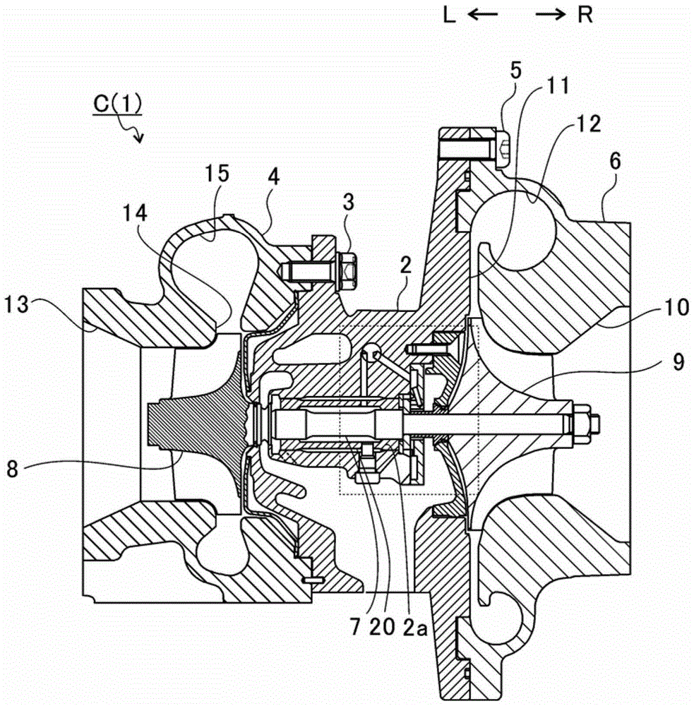
[0019] figure 1 is a schematic sectional view of the supercharger C. Below, with figure 1 The direction of the arrow L shown is the left side of the supercharger C, and the direction of the arrow R is the right side of the supercharger C. Such as figure 1 As shown, the supercharger C is configured by including a supercharger main body 1 . The supercharger main body 1 is...


PUM


Abstract

The present invention provides a supercharger comprising: a thrust bearing that is fixed to the supercharger main body with the opposing surface facing the thrust ring in the axial direction of the turbine shaft; and provided on the supercharger main body. , and a supply oil passage for supplying lubricating oil to the opposing surface of the thrust bearing. The thrust bearing has: an insertion hole through which the turbine shaft is inserted; a pressure receiving portion forming an oil film therebetween and receiving a thrust load using oil film pressure; and a plurality of interposed portions located between adjacent pressure receiving portions in the direction of rotation of the turbine shaft and farther from the thrust ring than the pressure receiving portion, At least a part of the interposed portion located vertically below the insertion hole has a surface that is farther from the thrust ring than the other intervened portions.

Description

technical field [0001] The present invention relates to a supercharger that receives a thrust load by utilizing a plurality of pressure receiving portions provided in a thrust bearing. Background technique [0002] A conventional supercharger includes a turbine shaft having a turbine wheel at one end and a compressor wheel at the other end. The turbine shaft is rotatably supported by the bearing housing. Such a supercharger is connected to the engine. The turbine impeller is rotated by the exhaust gas discharged from the engine, and the compressor impeller is rotated by the turbine shaft through the rotation of the turbine impeller. The engine is boosted by using the rotation of the compressor wheel to compress the air. [0003] The thrust bearing is disposed opposite to the thrust ring provided on the turbine shaft with the turbine shaft inserted through the insertion hole. The thrust bearing receives an axial load (thrust load) acting on the turbine shaft. On an oppos...

Claims


Application Information

Patent Timeline
Patent Type & Authority Patents(China)
IPC IPC(8): F02B39/14F02B39/00
CPCF01D25/166F01D25/168F05D2220/40F16C33/1045F16C2360/24F16C17/047F16C33/1075F01D25/16F04D29/0413
Inventor 采浦宽小池笃史小岛英之
Owner IHI CORP
Why Eureka
Try Eureka