
High-pressure-bearing pre-combustion chamber head shell structure

A technology of shell structure and pre-chamber, which is applied in the field of high-pressure pre-chamber head shell structure, and can solve the problems of overweight pre-chamber, spoiler ring or grid ablation, and increased diameter of fuel inlet pipe problems such as improving the pressure bearing capacity and structural reliability, reducing the weight of the pre-chamber, and reducing the weight of the pre-chamber

Pending Publication Date: 2018-04-17
BEIJING AEROSPACE PROPULSION INST
View PDF0 Cites 2 Cited by
  • Summary
  • Abstract
  • Description
  • Claims
  • Application Information

AI Technical Summary

Problems solved by technology

This brings new problems to the structural design of the pre-chamber: an increase in the flow rate of the pre-chamber will lead to an increase in the diameter of the fuel inlet pipe, which makes it difficult to arrange the pre-chamber fuel collector; the increase in the pressure of the pre-chamber requires pre-combustion The chamber head shell has sufficient pressure bearing capacity. According to the conventional design method, the wall thickness of the pre-chamber head shell will be significantly increased, which will lead to the overweight of the pre-chamber
[0004] As the flow rate increases, the uniformity of the temperature at the outlet of the pre-chamber is not easy to ensure
At present, in order to ensure the uniformity of the outlet temperature of the pre-combustion chamber, measures such as spoiler rings or grilles are generally used on the body of the combustion chamber, or measures for turning the body. On the one hand, the structure is more complicated, resulting in an increase in overall weight. On the other hand , the spoiler ring or grille may have ablated failure

Method used


Image

  • High-pressure-bearing pre-combustion chamber head shell structure
  • High-pressure-bearing pre-combustion chamber head shell structure

Examples


Embodiment Construction

[0023] The present invention will be described in detail below with reference to the drawings.

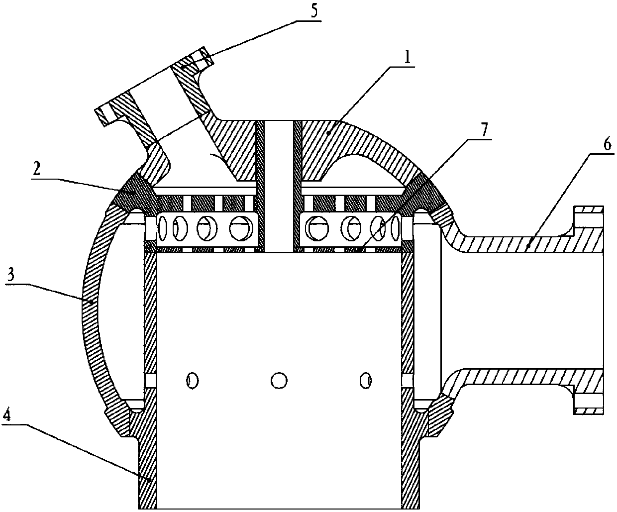
[0024] Such as figure 1 , figure 2 As shown, the head shell structure of the high-pressure pre-combustion chamber of the present invention is mainly composed of a top cover 1, a second bottom 2, a fuel collector 3, a body 4, an oxidizer flange 5, a fuel flange 6 and a bottom 7 composition, the shape is spherical, the pressure bearing of the spherical structure is not less than 20MPa. The top cover 1 is welded above the second bottom 2, the body is welded below the second bottom 2, the upper end of the fuel collector 3 is connected to the second bottom 2, the lower end of the fuel collector 3 is connected to the body 4, and the oxidizer flange 5 is connected to the top cover 1, and the fuel flange is connected to the fuel collector 3.

[0025] The top cover 1 of the pre-chamber is obtained by adding a raw material machine. The top machine adds a platform surface for connecting with th...


PUM


Abstract

The invention discloses a high-pressure-bearing pre-combustion chamber head shell structure. The structure comprises a top cover, a second bottom, a fuel collector, a body part and a first bottom, a pre-combustion chamber head shell adopts a spherical structure, so that the partial working environment of the body part is improved, the overall pressure bearing capacity and structural reliability ofa head of a pre-combustion chamber are improved, and structure arrangement of the fuel collector is facilitated; and the body part adopts a variable wall thickness design, and radial through-holes are uniformly formed in the portion, wrapped in the fuel collector, of the body part, so that part of fuel can directly enter the combustion chamber through the radial through-holes to be mixed with thehigh-temperature fuel gas so as to improve the uniformity of the temperature field at the outlet of the combustion chamber, meanwhile, structures such as a flow disturbing ring, a grid and an elbow of the body part are eliminated, and the weight of the pre-combustion chamber is effectively reduced.

Description

Technical field [0001] The invention relates to a high-pressure pre-combustion chamber head shell structure, which can be used in the field of liquid rocket engines. Background technique [0002] As a key component of the liquid rocket engine, the pre-combustion chamber is used to combust the oxidant and fuel entering the pre-combustion chamber at a certain mixing ratio to produce high-temperature gas to drive the turbo pump. [0003] The existing pre-chamber / gas generator has a small fuel flow rate, and a collector with the same height as the fuel chamber is usually designed outside the fuel chamber. As the thrust of the liquid rocket engine gradually increases, the flow rate and pressure of the pre-chamber will gradually increase. improve. This brings new problems to the structural design of the pre-chamber: an increase in the flow of the pre-chamber will lead to an increase in the diameter of the fuel inlet pipe, which will make it difficult to arrange the pre-chamber fuel coll...

Claims


Application Information

Patent Timeline
Patent Type & Authority Applications(China)
IPC IPC(8): F02K9/62
CPCF02K9/62
Inventor 潘刚丁兆波牛旭东潘亮马志瑜卢明孙纪国郑孟伟刘红珍张晋博许晓勇刘倩孔维鹏
Owner BEIJING AEROSPACE PROPULSION INST
Learn More