
Sponge placement bracket

A technology of sponge wipe and body, which is applied in the direction of cleaning carpets, floors, and cleaning equipment. It can solve the problems of large contact area between the sponge wipe and the bracket body, affecting the moisture of the sponge wipe, and easy to breed bacteria, so as to prevent breeding Bacteria, increase the area, and facilitate the seepage of water

Inactive Publication Date: 2018-04-17
HENAN ZHIYING ELECTRONICS TECH CO LTD
View PDF0 Cites 0 Cited by
  • Summary
  • Abstract
  • Description
  • Claims
  • Application Information

AI Technical Summary

Problems solved by technology

[0003] Yet existing a kind of sponge wipe placement bracket still has certain deficiencies in use, when in use, sponge wipe can not satisfy the function of being easy to move under the situation of being convenient to fixed function, and sponge wipe and place The contact area between the bracket bodies is too large, which affects the seepage of moisture inside the sponge wipe, and the sponge wipe is placed inside the bracket for a long time, which is easy to breed bacteria and affects the use

Method used


Image

  • Sponge placement bracket
  • Sponge placement bracket
  • Sponge placement bracket

Examples


Embodiment Construction

[0019] The following will clearly and completely describe the technical solutions in the embodiments of the present invention with reference to the accompanying drawings in the embodiments of the present invention. Obviously, the described embodiments are only some, not all, embodiments of the present invention.

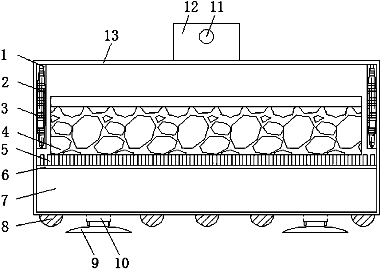
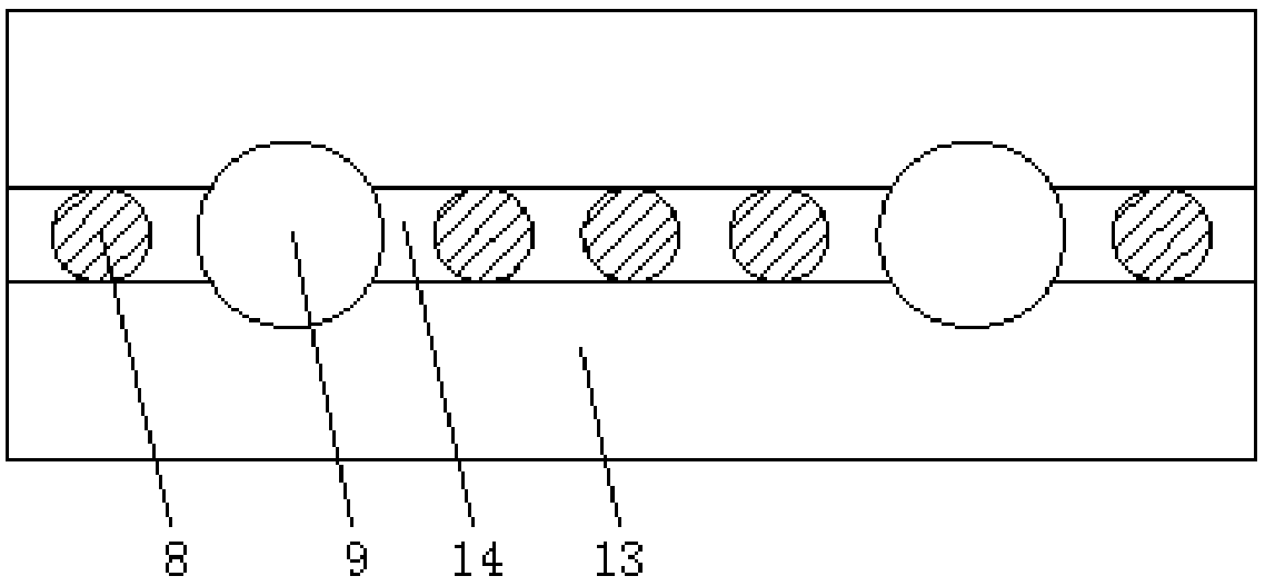
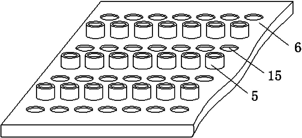
[0020] refer to Figure 1-3 , a sponge wipe placement bracket, including a permeable pipe 5 and a bracket body 13, a rolling groove 14 is provided at the horizontal midline position of the bottom of the bracket body 13, and a plurality of balls 8 are equidistantly arranged inside the rolling groove 14 The top of the bracket body 13 is symmetrically fixed with a telescopic column 10, the top of the telescopic column 10 is fixed with a suction cup 9, the inside of the bracket body 13 is provided with a water storage bin 7, and the inside of the bracket body 13 is located above the water storage bin 7 A base plate 6 is fixed at the top of the base plate 6, and a plurali...


PUM


Abstract

The invention discloses a sponge wipe placing bracket, comprising a water permeable pipe and a placing bracket body. A rolling groove is opened at the bottom horizontal centerline of the placing bracket body, and a plurality of rolling grooves are equidistantly arranged inside the rolling groove. The top of the placing bracket body is symmetrically fixed with a telescopic column, the top of the telescopic column is fixed with a suction cup, and the inside of the placing bracket body is provided with a water storage bin. In the present invention, a bottom plate is fixed inside the placing bracket body, the top of the bottom plate is provided with a plurality of permeable holes equidistantly, and a permeable pipe is fixed between every two permeable holes, the permeable pipe is connected with the bottom plate, and the sponge The wiper is placed on the top of the permeable pipe to reduce the contact area between the sponge wiper and the placing bracket body, which facilitates the infiltration of water inside the sponge wiper, and increases the area of ​​the permeable holes on the bottom plate, which is more conducive to the infiltration of water and accelerates The speed at which the sponge pad dries.

Description

technical field [0001] The invention relates to the technical field of placing brackets, in particular to a sponge wipe placing bracket. Background technique [0002] With the continuous improvement of people's living standards, people's requirements for the convenient use of materials are also getting higher and higher. In every family, housewives need to wipe the furniture at home, so as not to leave it for too long, resulting in dust everywhere , generally use sponge wipe to wipe now, need a kind of sponge wipe placement bracket to place sponge wipe. [0003] Yet existing a kind of sponge wipe placement bracket still has certain deficiencies in use, when in use, sponge wipe can not satisfy the function of being easy to move under the situation of being convenient to fixed function, and sponge wipe and place The contact area between the bracket bodies is too large, which affects the seepage of moisture inside the sponge wipe, and the sponge wipe is placed inside the brack...

Claims


Application Information

Patent Timeline
Patent Type & Authority Applications(China)
IPC IPC(8): A47L13/51
CPCA47L13/51
Inventor 杨英虎
Owner HENAN ZHIYING ELECTRONICS TECH CO LTD
Learn More