
High-temperature-resistant and corrosion-resistant stable roller

A corrosion-resistant and high-temperature-resistant technology, which is applied in the field of hot-dip galvanizing, can solve the problems of time-consuming and troublesome assembly or disassembly of rollers and roller shafts, time-consuming and laborious assembly or disassembly, and small cross-sectional area of ​​zinc liquid flow, etc., to achieve assembly Or it is convenient and quick to disassemble, easy to disassemble, and reduce the effect of sticky residue

Inactive Publication Date: 2018-04-13
江苏亚太特种铸钢厂有限公司
View PDF0 Cites 0 Cited by
  • Summary
  • Abstract
  • Description
  • Claims
  • Application Information

AI Technical Summary

Problems solved by technology

[0002] The stabilizing roll on the existing hot-dip galvanizing device generally includes a roller and a roller shaft connected to both ends of the roller. The roller shaft is inserted into the inner hole at the end of the roller and fixedly connected. It takes time and trouble to assemble or disassemble the shaft; second, the cross-sectional area of ​​the zinc liquid passing through is small, and the zinc liquid cannot pass through the cavity of the roller smoothly; third, after measures are taken to prevent the connection of the roller and the roller shaft from loosening However, it is time-consuming and laborious to assemble or disassemble the rollers and roller shafts

Method used


Image

  • High-temperature-resistant and corrosion-resistant stable roller
  • High-temperature-resistant and corrosion-resistant stable roller
  • High-temperature-resistant and corrosion-resistant stable roller

Examples


Embodiment Construction

[0024] The present invention will be further described below according to the accompanying drawings and in conjunction with the embodiments.

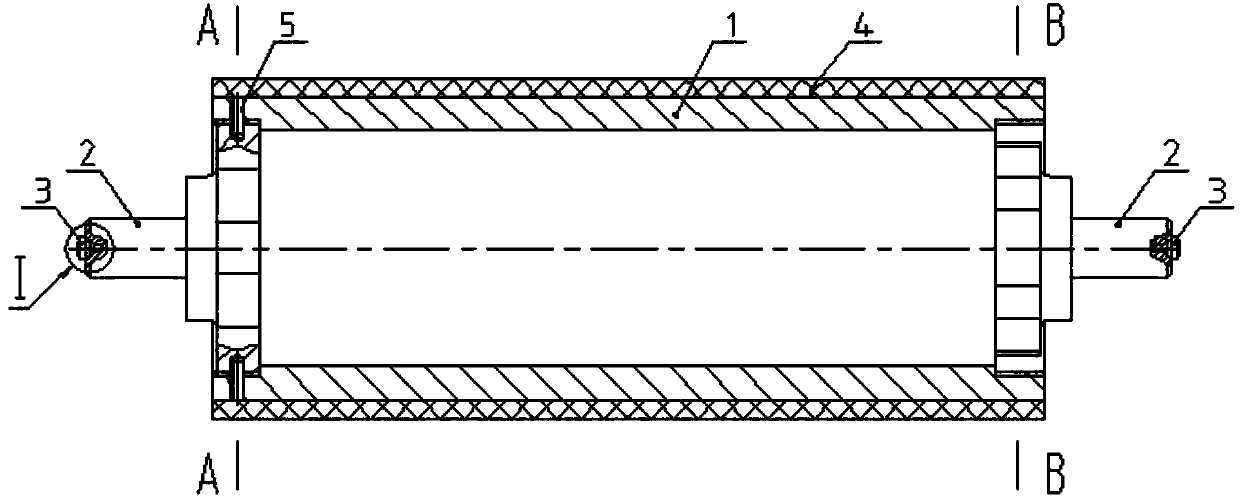
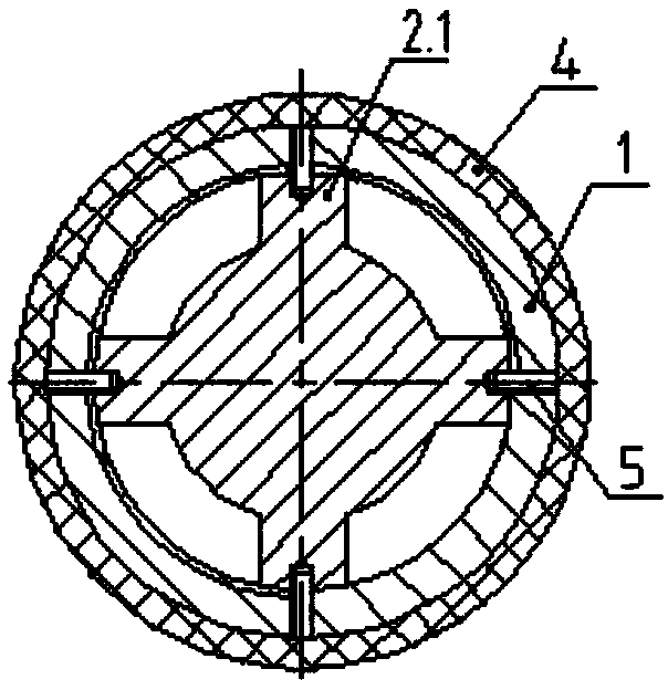
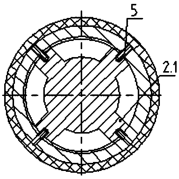
[0025] The high-temperature-resistant and corrosion-resistant stabilizing roller shown in the accompanying drawings includes a roller 1 and a roller shaft 2 connected to both ends of the roller 1; the end of the roller shaft 2 connected to the roller 1 is made of four webs 2.1 evenly distributed on the circumference Radial plate structure (in other embodiments, the end connecting the roller shaft 2 and the roller 1 is a radial plate structure with 3 or more than 4 radial plates 2.1 uniformly distributed on the circumference); the outer circumference of the radial plate 2.1 is provided with external threads , and threadedly connected with the inner threaded hole at the end of the roller 1.

[0026] There are 4 anti-loosening screws 5 at the threaded joint between the inner threaded hole at the end of the roller 1 and the threaded plate 2...


PUM


Abstract

The invention discloses a high-temperature-resistant and corrosion-resistant stable roller, which comprises a roller and a roller shaft connected to both ends of the roller; the end connected to the roller shaft and the roller is a radial plate structure in which more than three radial plates are evenly distributed on the circumference; There is an external thread on the outer circumference of the spoke plate, which is threadedly connected with the internal threaded hole at the end of the roller; more than one anti-loosening screw is provided at the thread connection between the internal threaded hole at the end of the roller and the threaded plate of the roller shaft; further improvement lies in: anti-loosening screw The number is the same as the number of roller shaft webs, and they are evenly distributed in the circumferential direction of the inner threaded hole wall at the end of the roller; the end of the roller shaft away from the roller is provided with a center hole, and plugging is installed in the center hole; the webs of the roller shafts at both ends are in the The central axis of the rollers is staggered in the circumferential direction; the outer wall of the roller is covered with a cobalt-based alloy roller sleeve. The invention effectively prevents the loose connection of the roller and the roller shaft, and at the same time, the assembly or disassembly of the roller and the roller shaft is convenient and fast, and is corrosion-resistant, heat-resistant and high-temperature-resistant.

Description

technical field [0001] The invention relates to the technical field of hot-dip galvanizing, in particular to a stabilizing roll on a hot-dip galvanizing device. Background technique [0002] The stabilizing roll on the existing hot-dip galvanizing device generally includes a roller and a roller shaft connected to both ends of the roller. The roller shaft is inserted into the inner hole at the end of the roller and fixedly connected. It takes time and trouble to assemble or disassemble the shaft; second, the cross-sectional area of ​​the zinc liquid passing through is small, and the zinc liquid cannot pass through the cavity of the roller smoothly; third, after measures are taken to prevent the connection of the roller and the roller shaft from loosening But it takes time and trouble to assemble or disassemble the roller and roller shaft. Contents of the invention [0003] The present invention aims at the deficiencies of the prior art, and provides a method that can signi...

Claims


Application Information

Patent Timeline
IPC IPC(8): C23C2/06
CPCC23C2/003C23C2/06
Inventor 贲启轩沈炳辉
Owner 江苏亚太特种铸钢厂有限公司
Learn More